
Printing head structure of 3D printer

A printing head and guide mechanism technology, applied in the field of additive manufacturing, can solve the problems affecting the performance and life of the nozzle structure of the printing head, the temperature field affecting the effective extrusion of the feeding material, and the length of the guide tube, etc., to achieve a reasonable temperature distribution, The effect of prolonging the service life and increasing the heat dissipation

Inactive Publication Date: 2017-05-10
SHANGHAI AUTOMATION INSTRAION CO LTD
View PDF0 Cites 2 Cited by
  • Summary
  • Abstract
  • Description
  • Claims
  • Application Information

AI Technical Summary

Problems solved by technology

However, the working temperature of the feeding mechanism and guide tube of the traditional printing head nozzle is too high, which is at the semi-melting temperature of the material. The unreasonable distribution of the temperature field seriously affects the effective extrusion of the feeding material, which can easily cause the material feeding in the printing head nozzle. The blockage of the pipeline affects the service performance and life of the entire print head nozzle structure, and the length of the feeding guide tube is usually relatively long, so it is difficult to process in actual production

Method used


Image

  • Printing head structure of 3D printer
  • Printing head structure of 3D printer

Examples


Embodiment Construction

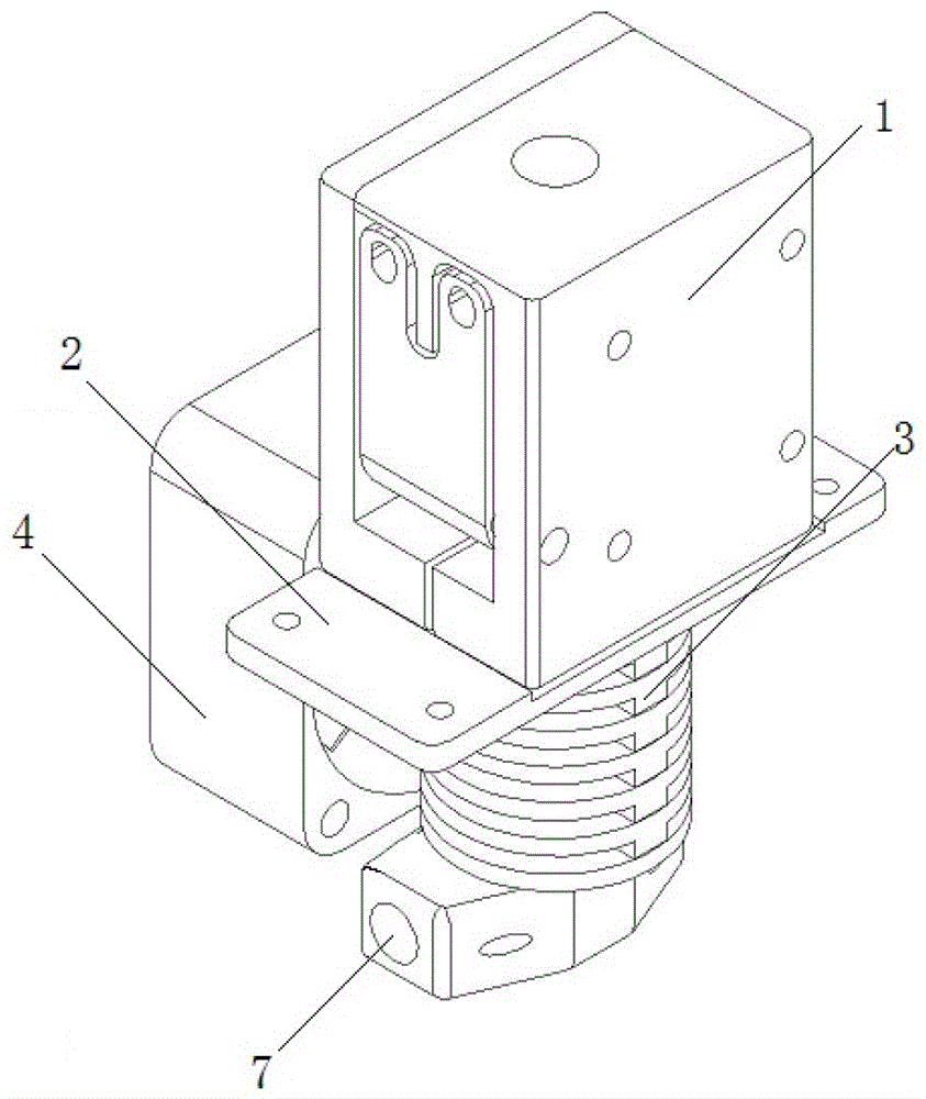
[0015] figure 1 It is a structural representation of the present invention. As shown in the figure, the entire print head structure includes a feeding mechanism 1, a mounting plate 2, a printing head mechanism 3, and a fan 4. The feeding mechanism 1 is installed on the mounting plate 2, with a feeding hole on the top and a discharge hole on the bottom. hole, the mounting plate 2 has a feeding hole; the fan 4 is installed on the side of the print head mechanism 3.

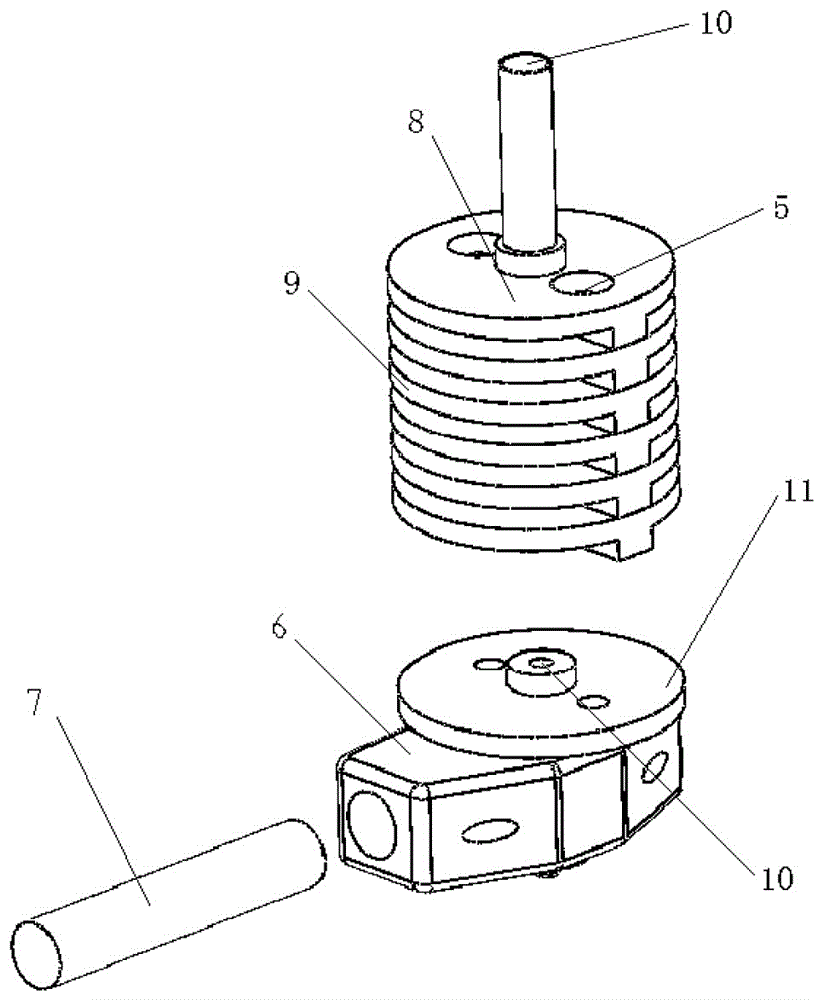
[0016] figure 2 It is a schematic diagram of the exploded structure of the printing head mechanism of the present invention. The print head mechanism 3 shown in the figure includes a heat dissipation guide mechanism, a print head nozzle 6 and a heating rod 7, and the heat dissipation guide mechanism is composed of a feeding connection plate 8, a plurality of heat sinks 9 and an installation platform 11 placed on the print head nozzle 6 , the feeding connection plate 9 located at the uppermost end of the heat dis...


PUM


Abstract

The invention relates to a printing head structure of a 3D printer, and belongs to the technical field of the additive manufacturing. In order to solve the problems that the printer is uniformly cooled and interior conveying pipes are difficultly machined, the printing head structure of the 3D printer comprises a conveying mechanism, an installing plate and a printing head mechanism. The conveying mechanism, the installing plate and the printing head mechanism are successively connected from top to bottom. The top of the conveying mechanism is provided with a feed opening, and the bottom is provided with a discharge opening. The position of the discharge opening is matched with the position of the conveying hole in the installing plate. The printing head mechanism comprises a cooling guide mechanism, a printing head nozzle and an installing platform thereof. A conveying hole is installed in each of a conveying connection plate and a cooling fin of the cooling guide mechanism. Each conveying hole is coaxially installed and mutually sheathed in series, for forming the interior conveying pipes of the printing head mechanism which directly connect with the nozzle opening. The cooling fin uses the split-type structure of the multi-fin superposition. The printing head temperature field of the printing head structure of the 3D printer is uniformly and rationally distributed, and the conveying pipes are conveniently machined and maintained.

Description

technical field [0001] The present invention relates to Fused Deposition Rapid Prototyping (FDM) equipment (commonly known as 3D printer) in the field of additive manufacturing, and in particular to an improvement of a print head structure, a key component of a 3D printer. Background technique [0002] The final output device of the 3D printer is the nozzle of the print head. In addition to the accuracy of the nozzle aperture, its structural design also affects the quality of the final molding and the convenience of the use process. The working principle of the hot-melt 3D printing nozzle is to use the roller to transport the solid material filament to the nozzle through the guide sleeve. The nozzle will generate high temperature to make the material filament change from solid to molten state and then extrude. Solidification, thus enabling material accumulation (3D printing). However, the working temperature of the feeding mechanism and guide tube of the traditional printin...

Claims


Application Information

Patent Timeline
IPC IPC(8): B29C64/20B29C64/209B29C64/321B29C64/295B33Y30/00B33Y40/00
CPCB29C31/00B29C35/02B33Y30/00B33Y40/00
Inventor 谈卓雅黄寅赖庆峰
Owner SHANGHAI AUTOMATION INSTRAION CO LTD
Features
  • Generate Ideas
  • Intellectual Property
  • Life Sciences
  • Materials
  • Tech Scout
  • Unparalleled Data Quality
  • Higher Quality Content
  • 60% Fewer Hallucinations
Learn More