Solar power ship

A solar energy and solar cell technology, applied in the field of cruise ships, can solve the problems of insufficient battery charging, discharge of waste water to pollute rivers, and high noise of fuel-powered ships, so as to ensure stability and safety, ensure normal operation time, and save parking space. Effect

Active Publication Date: 2017-05-10
陈光友
View PDF7 Cites 2 Cited by
  • Summary
  • Abstract
  • Description
  • Claims
  • Application Information

AI Technical Summary

Problems solved by technology

[0002] At present, the power boats used for sightseeing and tourism are mainly fuel-powered boats and a small number of electric-powered boats are supplemented. The boat needs to be charged in advance before operation. Due to the limitation of charging equipment and site, it cannot travel far, let alone meet the requirements of long-distance use.
[0003] Solar boats have attracted much attention from the industry for their clean energy. After years of research and development and experiments, the structure of solar boats has been initially finalized. The power storage device is at the bottom of the hull, and the roof of the hull is equipped with solar cells. Converted into electrical energy, the current of the solar cell module is collected through the confluence and sent to the solar controller, and the solar controller charges the battery. The existing solar boat mainly uses the roof solar module array as the source of energy, which is limited by the roof area. And the energy converted is often difficult to support the use of high-power motors on the hull, especially in the case of insufficient sunlight, the battery will be insufficiently charged, and the normal running time of the solar boat cannot be guaranteed. Only by increasing the lighting area and increasing the storage capacity can the solar energy be guaranteed. Ship running time is an important factor related to the popularization of solar ships

Method used


Image

  • Solar power ship
  • Solar power ship
  • Solar power ship

Examples


Embodiment 1

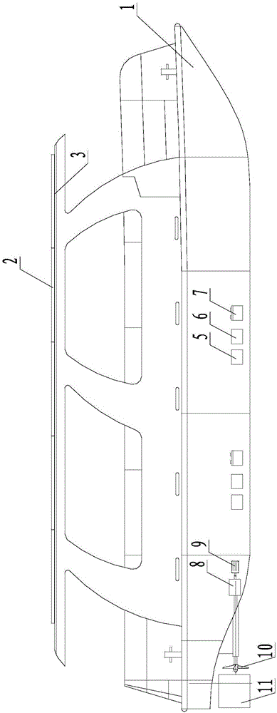
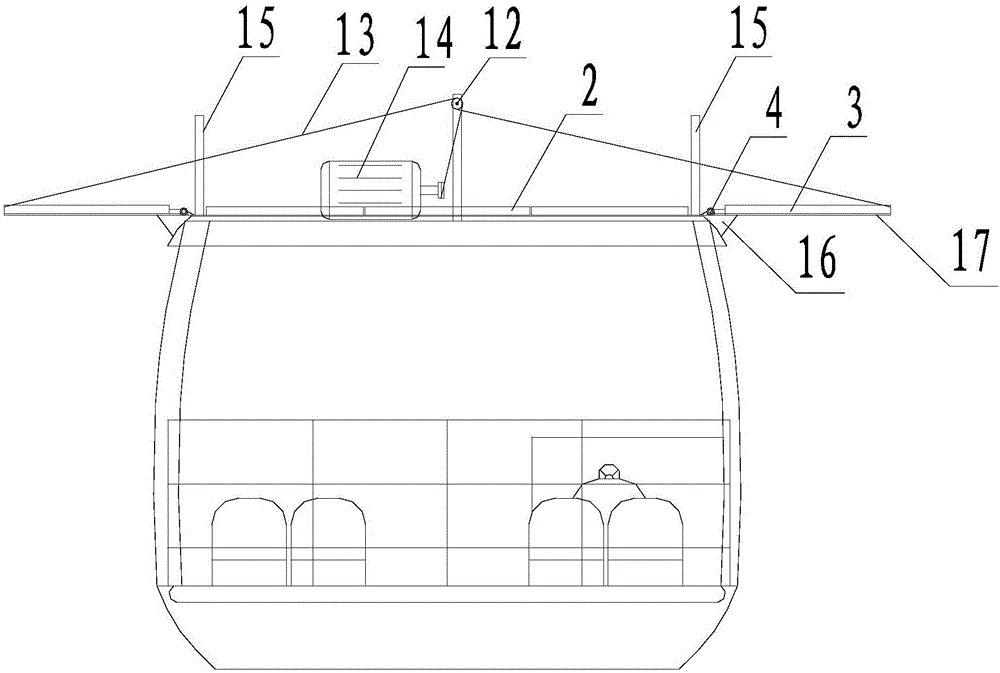
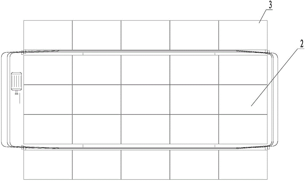
[0028] Refer to attached Figure 1 to Figure 7 As shown, a solar powered ship provided by the present invention includes a hull 1 with a roof, on which a solar panel assembly 2 is arranged, side wing brackets and supports movably connected with the side wing brackets are installed on both sides of the roof Seat, through the side wing support 17 is provided with the side wing solar cell assembly 3, the ceiling 1 is equipped with a lifting control assembly, the lifting control assembly and the side wing support are connected with a connecting piece, and the connecting piece side wing support is realized by driving the connecting piece through the lifting control assembly To open or fold, the lifting control assembly includes a motor 14, a fixed rod fixed on the ceiling and a fixed pulley 12 installed on the fixed rod. 14 It can be installed with a plurality of take-up and pay-off pulleys arranged in sequence. The take-up and take-off pulleys can rotate synchronously. The other e...

Embodiment 2

[0039] This embodiment is basically the same as Embodiment 1, the difference is that the limit mechanism includes a limit seat 27, the limit seat 27 is provided with an inner cavity with an opening, and two inner concave through grooves are opened on both sides of the inner cavity. The through groove has an aisle that communicates with the inner cavity, and a movable limit rod 20 is provided in the inner cavity. There is a ball hole 201 on the circumference of the rotating shaft above the limit seat, and the limit rod 20 has a The rolling ball 21 has a through hole at the bottom of the limit seat, and a driver 28 that can drive the limit rod to move up and down is placed in the through hole. One end of the driver 28 is located in the inner cavity and conflicts with the limit rod, and the other end Placed on the outside of the limit seat as the driving end of the drive limit rod, an elastic buffer part is also provided between the drive part and the limit rod, and the two ends o...


PUM


Abstract

The invention provides a solar power ship. The solar power ship is used for solving technical problems. The solar power ship comprises a ship body with a ceiling, and a solar cell assembly is arranged on the ceiling. The solar power ship is characterized in that side wing supports and supporting bases movably connected with the lateral wing supports are installed on the sides of the ceiling, side wing solar cell assemblies are arranged on the side wing supports, a lifting control assembly is installed on the ceiling, and connecting parts are connected between the lifting control assembly and the side wing supports and enable the side wing supports to be unfolded or folded under working of the lifting control assembly. Electric upward-turning devices are additionally arranged on the two sides of the solar cell assembly to unfold the side wing solar cell assemblies which are on the same horizontal plane with the solar cell assembly on the ceiling. By increasing daylighting area, power storage, power supply and duration capacity is improved, the normal running time of the solar power ship is guaranteed, and supporting mechanisms of the side wing solar cell assemblies guarantee the stability and safety of the side wing solar cell assemblies after unfolding.

Description

technical field [0001] The invention relates to medium and low-speed yachts and cruise ships sailing around the world, in particular to an electric ship with solar energy as the main power source. Background technique [0002] At present, the power boats used for sightseeing and tourism are mainly fuel-powered boats and a small number of electric-powered boats are supplemented. The boat needs to be charged in advance before operation. Due to the limitation of charging equipment and site, it cannot travel far, let alone meet the requirements of long-distance use. [0003] Solar boats have attracted much attention from the industry for their clean energy. After years of research and development and experiments, the structure of solar boats has been initially finalized. The power storage device is at the bottom of the hull, and the roof of the hull is equipped with solar cells. Converted into electrical energy, the current of the solar cell module is collected through the conf...

Claims


Application Information

Patent Timeline
Patent Type & Authority Applications(China)
IPC IPC(8): B63H21/17H02S20/30
CPCB63H21/17B63H2021/171H02S20/30Y02E10/50
Inventor 陈光友
Owner 陈光友
Why Eureka
Try Eureka