Ground guiding type unmanned aerial vehicle flying landing system and method based on LED dot matrix

An unmanned aerial vehicle, guided technology, applied to ground devices, control/adjustment systems, aircraft parts, etc., can solve problems such as non-functioning, high difficulty, and complex image processing algorithms, to avoid loosening and improve protection. , the effect of improving the tightness

Active Publication Date: 2017-05-10
SHANDONG UNIV +1
View PDF8 Cites 17 Cited by
  • Summary
  • Abstract
  • Description
  • Claims
  • Application Information

AI Technical Summary

Problems solved by technology

[0006] First, the existing technology is to install the camera on the UAV, and capture the geographical location characteristics of the landing point through the camera on the UAV, which puts forward higher requirements on the computing speed of the UAV onboard processor. It is necessary to use a high-speed and high-power dedicated processor for image processing and algorithm calculation, which increases the overall power consumption of the UAV, which greatly reduces the flight radius of the UAV when performing tasks;
[0007] Second, the existing technology is to install the camera on the UAV. During the flight of the UAV, the shaking of the fuselage will affect the camera's camera angle and definition, making the image processing algorithm complex and difficult, so that the Unfavorable effects of precise landing of drones;
[0008] Third, the existing technology installs the camera on the drone, which cannot work normally in the environment of weak external light and near zero light intensity at night, and the existing technology cannot realize the all-weather precise landing function

Method used


Image

  • Ground guiding type unmanned aerial vehicle flying landing system and method based on LED dot matrix
  • Ground guiding type unmanned aerial vehicle flying landing system and method based on LED dot matrix
  • Ground guiding type unmanned aerial vehicle flying landing system and method based on LED dot matrix

Examples


Embodiment Construction

[0118] The present invention will be further described below in conjunction with the accompanying drawings and embodiments.

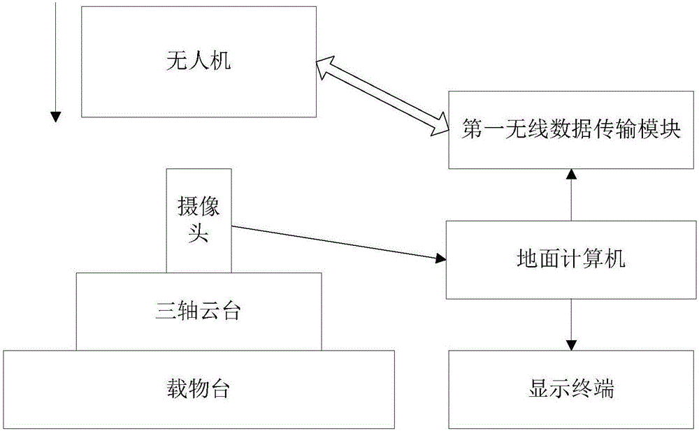
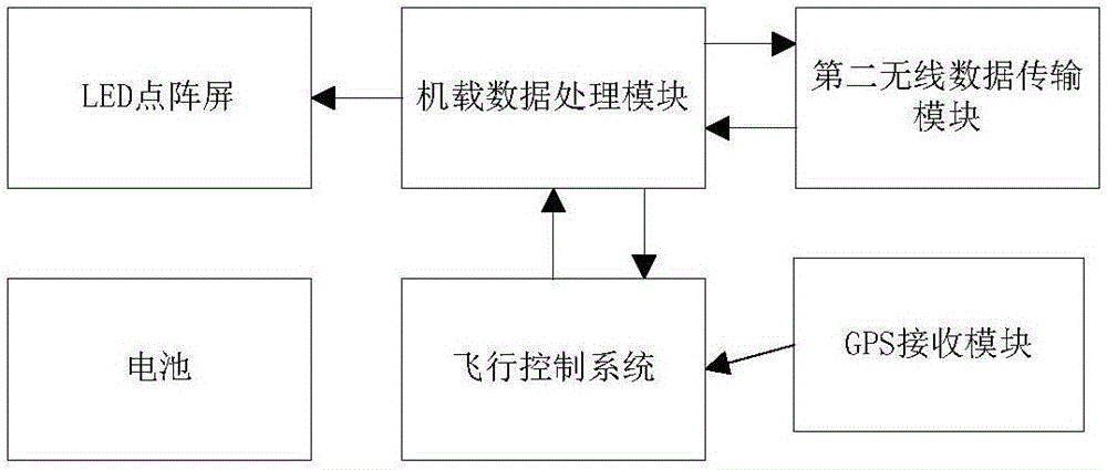
[0119] Such as figure 1As shown, the ground-guided UAV flight and landing system based on LED dot matrix includes: UAV and UAV landing station, and the UAV landing station includes a loading platform, and auxiliary equipment is installed on the loading platform. The precise positioning and fixing device for the landing of the drone, the precise positioning and fixing device for assisting the landing of the drone are installed with a three-axis pan-tilt, and a camera is installed on the three-axis pan-tilt, and the camera is always under the control of the pan-tilt Keeping the lens facing up and in the same direction, the camera is connected to the ground computer; the ground computer controls the camera to take pictures; the ground computer communicates with the UAV through the first wireless data transmission module; the computer also communicates with...


PUM


Abstract

The invention discloses a ground guiding type unmanned aerial vehicle flying landing system and method based on an LED dot matrix. The system comprises an unmanned aerial vehicle and an unmanned aerial vehicle taking-off and landing station. The unmanned aerial vehicle taking-off and landing station comprises a carrying table, a three-axis pan-tilt is installed on the carrying table, and a camera is installed on the three-axis pan-tilt; a lens of the camera is controlled by the three-axis pan-tilt to be always kept upward and unchanged in direction, and the camera is connected with a ground computer; and the ground computer controls the camera to carry out photographing. The ground guiding type unmanned aerial vehicle flying landing system and method based on the LED dot matrix have the beneficial effect that an all-weather centimeter-level precise landing function of the multi-rotor unmanned aerial vehicle is achieved through the color and shape recognition algorithm of the computer vision technology and the multi-section PID control technology.

Description

technical field [0001] The invention belongs to the technical field of unmanned aerial vehicle control, and relates to a ground-guided unmanned aerial vehicle flight and landing system and method based on LED dot matrix. Background technique [0002] With the development of science and technology, multi-rotor UAVs have been widely used in many fields such as aerial photography, power inspection, geographic surveying and mapping, agricultural plant protection, security monitoring, emergency rescue and so on. At the same time, the technology related to drones has also developed rapidly, which has greatly promoted the improvement of productivity and living standards. [0003] At present, scientific and technological workers have conducted in-depth research on the flight control technology of multi-rotor UAVs, and have achieved fruitful results. However, the precise control of the landing stage of multi-rotor drones is still in the initial stage of research. The precise landing...

Claims


Application Information

Patent Timeline
Patent Type & Authority Applications(China)
IPC IPC(8): B64D45/08B64F5/00G05D1/10
CPCB64D45/08B64F5/00G05D1/101
Inventor 马思乐王军峰丁为杰赵月陈祥海丁为飞陈远方马晓静孙文旭张佰顺李金刚王勇
Owner SHANDONG UNIV
Why Eureka
Try Eureka