
Steel rail surface treatment system using laminar plasma

A laminar plasma, surface treatment technology, applied in coating, metal material coating process, melt spraying and other directions, to achieve the effect of low friction, improved wear resistance, and obvious effect of hardness enhancement

Inactive Publication Date: 2017-05-10
四川金虹等离子技术有限公司
View PDF10 Cites 5 Cited by
  • Summary
  • Abstract
  • Description
  • Claims
  • Application Information

AI Technical Summary

Problems solved by technology

[0005] In the past two hundred years, the surface strengthening and repairing of rails, hubs, turnouts, locomotive bearings, wheels, axles and other related track components has always been a hot spot in the world. However, due to its high performance, high melting point and unique use characteristics , traditional technologies and emerging technologies in recent decades cannot be used for surface repair and strengthening
The world's major industrial powers, such as the United States, Russia, Germany, Russia and other countries, invest a lot of manpower and material resources in the research of railway remanufacturing technology every year, but still have not fundamentally solved this problem. For now, Russia has made some progress in the application of traditional plasma-enhanced wheels, and the United States and China Railway Research Institute have also made partial application progress in laser-enhanced track surfaces, but in terms of fundamental practical applications, this is still an unbroken world problem

Method used


Image

  • Steel rail surface treatment system using laminar plasma
  • Steel rail surface treatment system using laminar plasma
  • Steel rail surface treatment system using laminar plasma

Examples

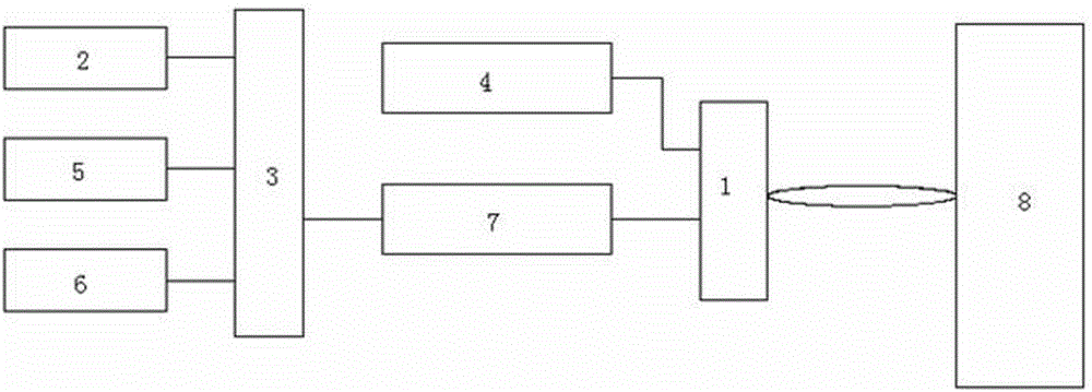
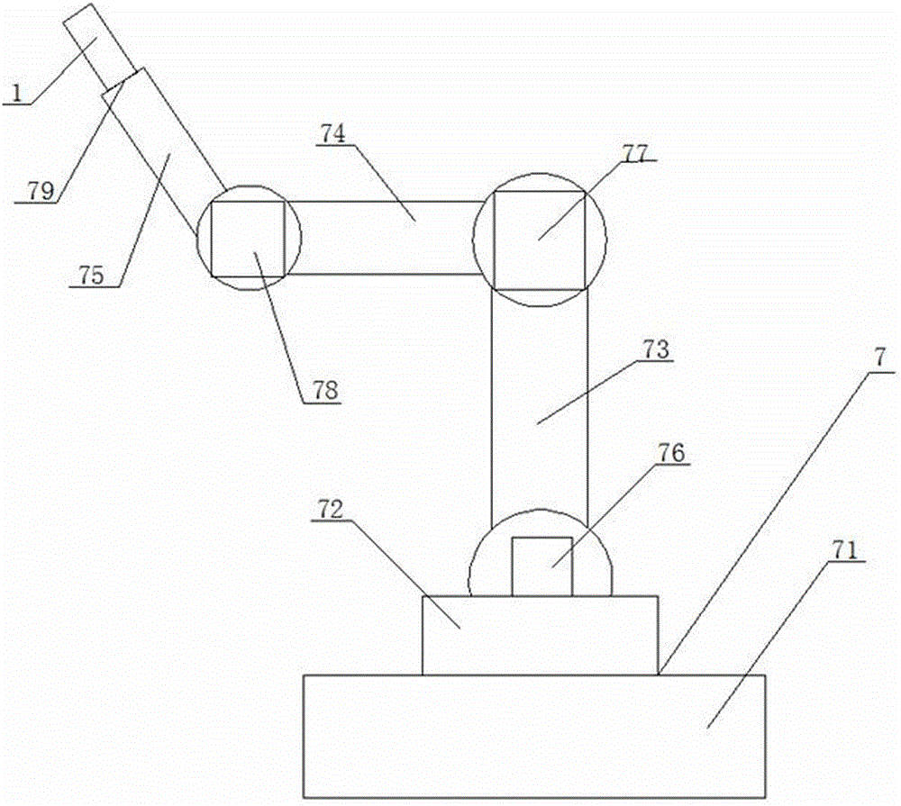

Embodiment 1

[0027] As a preferred embodiment of the present invention, with reference to the attached figure 1 , this example discloses:

[0028] A rail surface treatment system using laminar plasma, including a non-transferred arc laminar plasma beam spray gun 1, a high-frequency rectifier power supply 2, a control cabinet 3, a wire feeding device 4, a circulating water cooling device 5, and a gas supply device 6. The industrial robot 7 and the rail installation platform 8; the non-transferred arc laminar flow plasma beam spray gun 1 is installed on the execution end 79 of the industrial robot 7; the circulating water cooling device 5 is controlled by the control cabinet 3 and the non-transferred arc laminar flow The plasma beam spray gun 1 is used for cooling the non-transferred arc laminar flow plasma beam spray gun 1; the gas supply device 6 is controlled by the control cabinet 3, and is used to provide the non-transferred arc laminar flow plasma beam spray gun 1 with working gas, Th...

Embodiment 2

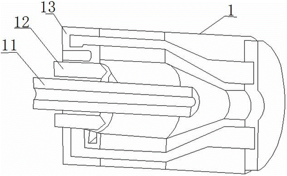
[0030] As another preferred embodiment of the present invention, with reference to the attached figure 1 and 2 , this example discloses:

[0031]A rail surface treatment system using laminar plasma, including a non-transferred arc laminar plasma beam spray gun 1, a high-frequency rectifier power supply 2, a control cabinet 3, a wire feeding device 4, a circulating water cooling device 5, and a gas supply device 6. The industrial robot 7 and the rail installation platform 8; the non-transferred arc laminar flow plasma beam spray gun 1 is installed on the execution end 79 of the industrial robot 7; the circulating water cooling device 5 is controlled by the control cabinet 3 and the non-transferred arc laminar flow The plasma beam spray gun 1 is used for cooling the non-transferred arc laminar flow plasma beam spray gun 1; the gas supply device 6 is controlled by the control cabinet 3, and is used to provide the non-transferred arc laminar flow plasma beam spray gun 1 with work...

Embodiment 3

[0035] As another preferred embodiment of the present invention, with reference to the attached figure 1 and 2 , this example discloses:

[0036] A rail surface treatment system using laminar plasma, including a non-transferred arc laminar plasma beam spray gun 1, a high-frequency rectifier power supply 2, a control cabinet 3, a wire feeding device 4, a circulating water cooling device 5, and a gas supply device 6. The industrial robot 7 and the rail installation platform 8; the non-transferred arc laminar flow plasma beam spray gun 1 is installed on the execution end 79 of the industrial robot 7; the circulating water cooling device 5 is controlled by the control cabinet 3 and the non-transferred arc laminar flow The plasma beam spray gun 1 is used for cooling the non-transferred arc laminar flow plasma beam spray gun 1; the gas supply device 6 is controlled by the control cabinet 3, and is used to provide the non-transferred arc laminar flow plasma beam spray gun 1 with wor...


PUM


Abstract

The invention discloses a steel rail surface treatment system using laminar plasma, and relates to the technical field of steel rail remanufacturing treatment. The system comprises a non-transfer arc laminar plasma beam spraying gun, a high-frequency rectifying power supply, a control cabinet, a wire and powder feeding device, a circulating water cooling device, a gas supply device, an industrial robot and a steel rail mounting platform; the non-transfer arc laminar plasma generator is used as a heat source, and performs a relatively parallel constant-speed motion along the longitudinal axis of a steel rail; the wire and powder feeding device axially feeds powder along the center of the non-transfer arc laminar plasma generator; and the surface of the steel rail mounted on the steel rail mounting platform is treated. The system adopts a laminar arc plasma beam remanufacturing system equipment to perform the heat surface reinforcement treatment for rail junctions, steel rails, wheels and other rail vehicle parts; and treated materials are more obvious in surface hardness reinforcement effect, and greatly improve the wear resistance.

Description

technical field [0001] The invention relates to the technical field of rail remanufacturing, in particular to a rail surface treatment system using laminar flow plasma. Background technique [0002] With the high-speed and heavy-duty rail transit in my country, the operating conditions of railways are becoming increasingly harsh, which makes the stress state of railways and their accessories and rail locomotive parts worse, accelerates the failure rate, and shortens the service life. The production of main parts and accessories of rail vehicles is in short supply. The production capacity of domestic enterprises can no longer meet the demand of the market. Some rail vehicle parts and accessories still need to be imported; Most of them are steel castings, and the surface treatment process is very complicated. Once they fail, they can only be returned to the furnace for treatment, and the recycling of the remaining value cannot be realized. [0003] With the continuous expansi...

Claims


Application Information

Patent Timeline
Patent Type & Authority Applications(China)
IPC IPC(8): C23C4/134
Inventor 李向阳黄佳华李露何泽
Owner 四川金虹等离子技术有限公司
Learn More