A track-laying machine with automatic span change during the traveling process and its application method

A track-laying machine and automatic technology, which is applied in the field of engineering technology and science, can solve the problems of labor and time-consuming, repeated disassembly and assembly, etc., and achieve the effect of realizing intrinsic safety, improving construction speed and reducing labor.

Active Publication Date: 2019-01-11
CHINA RAILWAY SHANGHAI ENGINEERING BUREAU GROUP CO LTD +3
View PDF1 Cites 1 Cited by
  • Summary
  • Abstract
  • Description
  • Claims
  • Application Information

AI Technical Summary

Problems solved by technology

[0003] The purpose of the present invention is to design a new type of track laying machine, which has automatic span change when empty and heavy load, automatic contraction of the height and width of the whole machine, and a track laying machine that can travel on both the gauge of the working section and the gauge of the main line. To solve the problems of repeated disassembly and assembly and labor-intensive entry and exit before and after the construction of the existing track-laying machine during frequent span-changing operations, it adopts the principle of power-driven contraction of the upper part and progressive offset and indentation of the lower part along the longitudinal track. Carry out optimization and improvement to achieve zero time-consuming for the track laying machine on the working surface of the subway track construction, without dismantling the working surface transfer and long-distance transfer transportation of the whole machine, electric retractable cables, automatic clamping and semi-automatic unloading of the rail row, greatly Improve ergonomics

Method used


Image

  • A track-laying machine with automatic span change during the traveling process and its application method
  • A track-laying machine with automatic span change during the traveling process and its application method
  • A track-laying machine with automatic span change during the traveling process and its application method

Examples


Embodiment 1

[0051] The utility model relates to the structural composition of an automatic span-changing track-laying machine during the traveling process.

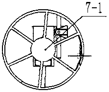
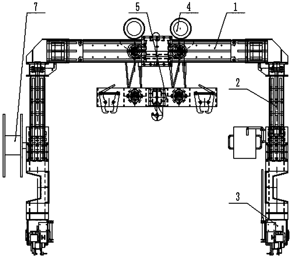
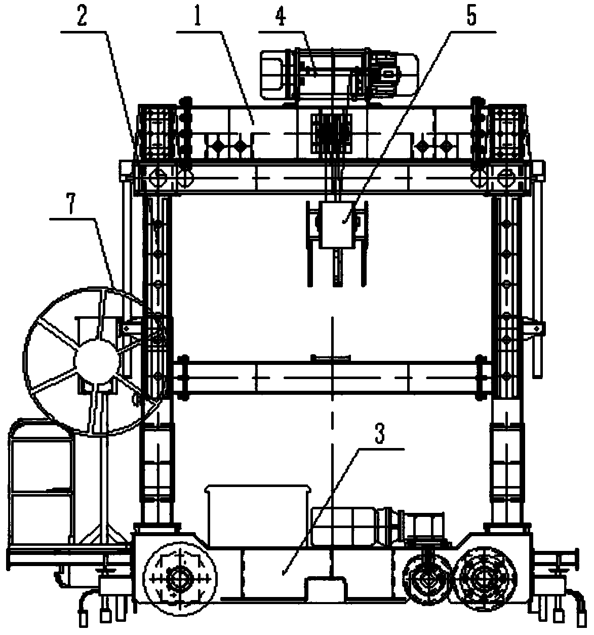
[0052] The design of the present invention is mainly composed of seven parts, which are: guide column type upper beam assembly 1, outrigger assembly 2, running beam assembly 3, lifting system 4, rail pole pole 5, and lateral movement variable span system 6 electrical control system, etc. Such as Figure 1a , 1b , 1c shown.

[0053] The guide column type upper beam assembly 1 is an "I"-shaped structure as a whole, and is composed of an upper beam connecting beam 1-1, an upper beam guide column 1-2, and an upper beam guide column extension section 1-3, and each part is A box structure made of welded plates. The middle parts of the two upper beam guide columns 1-2 are equipped with flanges, which are connected by the flanges at both ends of the upper beam connecting beam 1-1 to form an "I"-shaped structure, and the upper beam guide c...

Embodiment 2

[0063] How to use the automatic span-changing track-laying machine during the traveling process.

[0064] 1. The track laying machine is transported and hoisted to the site of the track laying base, rotated and stretched to connect the extension section 1-3 of the upper beam guide column, rotate the control panel to the operating position, debug the whole machine, hoist it down to the main line with the base crane, and use the rail car to pull through the main line. The line travels to the working surface of the track-laying section, and the track-laying machine is operated to raise it to the height required for the operation, and insert the outrigger guide sleeve 2-1 outrigger guide column 2-2 to connect the pin shaft.

[0065] 2. Install the transition rail from the main line to the section running rail, operate the track laying machine to automatically change the span along the transition rail to the section running rail 8-2, insert the upper beam guide sleeve 2-5, and the u...


PUM


Abstract

The invention relates to a track layer automatically changing the span in the advancing process and a use method. The track layer is characterized in that the track layer is composed of a guide column type upper crossbeam assembly, supporting leg assemblies, walking beam assemblies, a lifting system, a track panel carrying pole, a transversely-moving span changing system and an electrical control system. The whole guide column type upper crossbeam assembly is of an I-shaped structure. The lifting system is erected at the center of the guide column type upper crossbeam assembly. The left end and the right end of the guide column type upper crossbeam assembly are connected with the walking beam assemblies at the left end and the right end through the supporting leg assemblies vertically arranged at the left end and the right end. The guide column type upper crossbeam assembly and the supporting leg assemblies are each of a telescopic structure. Compared with the prior art, the upper crossbeam assembly and the supporting leg assemblies are connected through guide sleeves and guide columns, automatic span changing in the empty heavy load advancing process is achieved through the transversely-moving span changing system, no time is consumed during interval span changing, the track layer travels on a main track, labor is greatly saved, and the construction speed is greatly increased.

Description

[technical field] [0001] The invention belongs to engineering technology science, and relates to the design and use method of a rail laying machine for urban rail transit engineering. [Background technique] [0002] At present, in the track-laying construction of urban rail projects in my country, the traditional track-laying equipment mainly has two structural types: simple assembly and conversion type and manual and hydraulic power improved type. The simple track-laying machine for assembly and conversion needs to be shut down and disassembled before being assembled during the conversion and spanning process of the working surface. Due to the narrow space of the tunnel, it is difficult to hoist and change the span, and the work efficiency is low, labor-intensive and time-consuming; Although there is no need for disassembly during the process, it is necessary to stop the machine and manually raise and move the span at a low level. Although it saves the invalid time for chan...

Claims


Application Information

Patent Timeline
Patent Type & Authority Patents(China)
IPC IPC(8): E01B29/16E01B29/02
CPCE01B29/02E01B29/16E01B2203/14
Inventor 郑康海陈付平赵文君刘绩刘习生闫进虎李朝林陈再昌
Owner CHINA RAILWAY SHANGHAI ENGINEERING BUREAU GROUP CO LTD
Why Eureka
Try Eureka