Water well structure for foundation pit dewatering and construction method thereof

A technology for water well construction and water wells, which is applied in basic structure engineering, construction and other directions, can solve the problems of long construction period, inconvenient construction, and affect the safety of adjacent buildings, and achieves the effect of simple and practical construction method and short period.

Active Publication Date: 2017-05-10
CCFED THE FIRST CONSTR & ENG
View PDF5 Cites 3 Cited by
  • Summary
  • Abstract
  • Description
  • Claims
  • Application Information

AI Technical Summary

Problems solved by technology

[0003] The purpose of the present invention is to provide a foundation pit dewatering well structure and its construction method to solve the existing conventional construction site drainage method. The construction method has certain limitations, and the construction period is long. The construction of the covered site is inconvenient and affects the structural safety of adjacent buildings

Method used


Image

  • Water well structure for foundation pit dewatering and construction method thereof

Examples


Embodiment

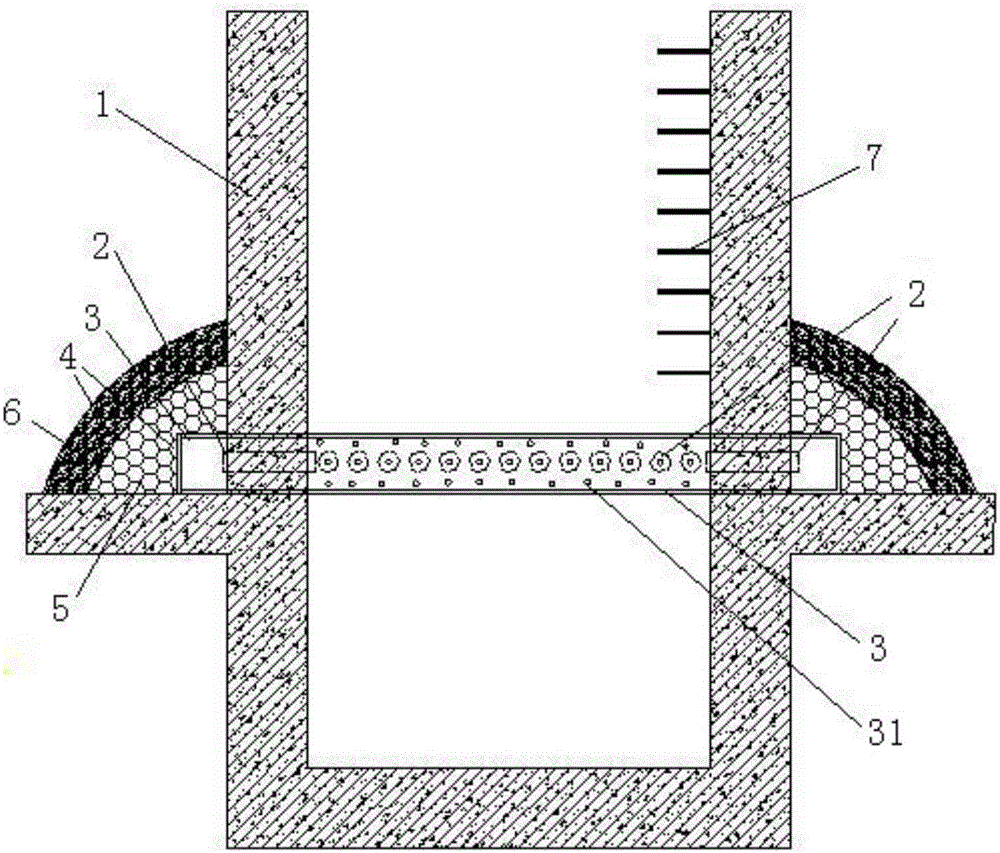
[0026] Refer to attached figure 1 , the present embodiment provides a foundation pit dewatering well structure, including a water well 1, the water well 1 is a square well structure, and the position distribution of 1m above the elevation of the bottom plate of the water well is installed with a water-passing steel casing 2 with a diameter of 100mm at a spacing of 150mm, and a water-passing steel The casing 2 runs through the side wall of the water well, and the outside of the water well 1 is installed and fixed with a permeable steel plate 3 through steel bars. The outer side of the water-passing steel casing 2, and the closed structure between the permeable steel plate 3 and the outer wall of the well 1, the type of channel steel used for the permeable steel plate 3 is 14b, that is, the height is 140mm, the leg width is 60mm, and the waist thickness is 8mm. The outer side of 3 lays geotextile 4, cobblestone 5, geotextile 4 and crushed stone filter layer 6 successively, and t...


PUM

PropertyMeasurementUnit
Diameteraaaaaaaaaa
Heightaaaaaaaaaa
Thick waistaaaaaaaaaa

Abstract

The invention provides a water well structure for foundation pit dewatering and a construction method thereof. The water well structure for foundation pit dewatering comprises a water well, water passing steel sleeves penetrating through the side wall of the water well are installed on the water well, and permeable steel plates are fixed to the outer side of the water well through steel bars. The outer sides of the water passing steel sleeves are covered with the permeable steel plates, and a closed type structure is formed between the permeable steel plates and the outer wall of the water well. Permeable holes are formed in the permeable steel plates, and earthwork fiber cloth, cobblestone, earthwork fiber cloth and a gravel filtering layer are sequentially paved on the outer sides of the permeable steel plates. According to the water well structure for foundation pit dewatering and the construction method thereof, the problems that an existing regular construction site drainage method has certain limitation and long in construction period, construction of a site with the surrounding site being covered by adjacent buildings is inconvenient, and structure safety of the adjacent buildings is influenced are solved. The invention belongs to the field of drainage construction.

Description

technical field [0001] The invention relates to a construction site water control structure and method, belonging to the field of drainage construction. Background technique [0002] Conventional water control at the construction site is mainly based on blockage removal. Drainage is to build drainage blind ditches or use tube wells to pump away groundwater. The construction of blind drainage ditches requires certain water pressure or artificial drainage slope, which has certain limitations for the construction method of blind drainage ditches in areas with large areas of water seepage and large construction areas. For water blocking (making water-stop curtain) and tube well dewatering, well point pipes need to be buried around the foundation pit. This method has a long construction period and is inconvenient for the site where the surrounding site is covered by adjacent buildings. And a large amount of groundwater was pumped away and discharged. The buoyancy of groundwate...

Claims


Application Information

Patent Timeline
IPC IPC(8): E02D19/10
CPCE02D19/10
Inventor 岳巍苏伟王立军刘辉
Owner CCFED THE FIRST CONSTR & ENG
Why Eureka
Try Eureka