Positioning device for anchor bolts and construction method of positioning device

A technology of positioning device and construction method, which is applied in the processing of building materials, construction, building structure, etc., can solve problems such as unfavorable concrete vibration, anchor bolt extrusion deviation, force consumption error, etc., to improve engineering construction efficiency. , the effect of high positioning accuracy and great promotion value

Pending Publication Date: 2017-05-10
DONGFENG DESIGN INST
View PDF6 Cites 2 Cited by
  • Summary
  • Abstract
  • Description
  • Claims
  • Application Information

AI Technical Summary

Problems solved by technology

However, during the construction process, the on-site problems caused by the inaccurate positioning of the anchor bolts at the column feet are one of the most frequently reported problems in steel structure construction.
Due to the uneven level of the construction team, the responsibilities of the civil engineering party and the steel structure party for pre-embedded anchor bolts are not clear, the disadvantages of making traditional anchor bolt positioning molds, and the concrete is easy to squeeze the anchor bolts and cause deviations, etc. Affected by the impact, the pre-embedded deviation of the anchor bolt is far greater than the allowable deviation range of the national standard (the national acceptance standard allows the center deviation of the anchor bolt at the

Method used


Image

  • Positioning device for anchor bolts and construction method of positioning device
  • Positioning device for anchor bolts and construction method of positioning device
  • Positioning device for anchor bolts and construction method of positioning device

Examples


Embodiment Construction

[0043] The present invention will be further described in detail below in conjunction with the accompanying drawings and specific embodiments.

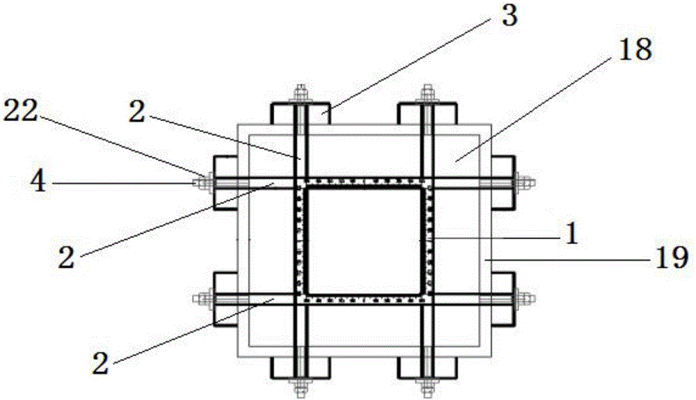
[0044] Such as image 3 The positioning device of the column foot anchor shown in -10 includes a pile body dial 1, and the pile body dial 1 is a closed rectangular ring with a scale on the circumferential top surface, such as Figure 4As shown, the measurement unit of the pile body dial 1 is mm, and the unit scale is accurate to 5mm. Two telescopic tubes 2 are respectively connected to the four corners of the pile body dial 1, and the end of the telescopic tube 2 is fixed with a device positioning block. 3. The device positioning block 3 is provided with a device positioning bolt 4, such as Figure 8 As shown, the two ends of the device positioning bolt 4 pass through the device positioning block 3, and one end of the device positioning bolt 4 is connected with a device positioning nut 22;

[0045] The front and rear opposite side s...


PUM


Abstract

The invention discloses a positioning device for anchor bolts. The positioning device comprises a pile body index dial. The outer wall of the pile body index dial is uniformly and circumferentially connected with telescopic tubes perpendicular to the surface of the outer wall of the pile body index dial at intervals. Device positioning blocks are fixed to the ends of the telescopic tubes. Device positioning bolts are arranged in the device positioning blocks correspondingly. A plurality of sets of first clamping strips capable of moving left and right are connected between the surfaces of the opposite inner walls of the front side and the rear side of the pile body index dial. Every two opposite semicircular grooves located in the two first clamping strips of the same set form a positioning groove matched with a thread on one anchor bolt. A plurality of sets of second clamping strips capable of moving front and back are connected between the surfaces of the opposite inner walls of the left side and the right side of the pile body index dial. Every two opposite semicircular grooves located in the two second clamping strips of the same set form a positioning groove matched with a thread on one anchor bolt. A gap exists between the first clamping strips and the second clamping strips in the longitudinal direction. The positioning device is simple in structure, easy to machine, high in positioning precision, easy to operate and capable of being recycled.

Description

technical field [0001] The invention relates to the technical field of construction engineering equipment, in particular to a positioning device for anchor bolts at column bases and a construction method thereof. Background technique [0002] With the wide application of steel structure buildings, it is often necessary to use column foot anchors to fix building steel columns or equipment in the foundation construction of construction projects. However, during the construction process, the on-site problems caused by the inaccurate positioning of the anchor bolts at the column feet are one of the most frequently reported problems in the construction of steel structures. Due to the uneven level of the construction team, the responsibilities of the civil engineering party and the steel structure party for pre-embedded anchor bolts are not clear, the disadvantages of making traditional anchor bolt positioning molds, and the concrete is easy to squeeze the anchor bolts and cause d...

Claims


Application Information

Patent Timeline
IPC IPC(8): E04G21/18
CPCE04G21/185
Inventor 蔡恺王正龙李长征唐琴琴王莉彭军波胡春丽
Owner DONGFENG DESIGN INST
Why Eureka
Try Eureka