A continuous cycle valve

A technology of circulating valve and valve body, which is applied in wellbore/well valve device, wellbore/well components, construction, etc., can solve the problems of reducing drilling time efficiency, economic loss, waste of non-working time, etc., so as to reduce non-operational effect of time

Active Publication Date: 2019-08-13
HUBEI HONGCHENG GENERAL MACHINERY
View PDF5 Cites 0 Cited by
  • Summary
  • Abstract
  • Description
  • Claims
  • Application Information

AI Technical Summary

Problems solved by technology

In order to prevent the occurrence of accidents such as leak leakage and collapse, continuous circulation valves are widely used in operations such as drilling, well completion, oil well maintenance, well washing, salvage, and packer setting. However, the current continuous circulation valves are limited by the number of cycles Due to the limitation of tripping and replacing the non-continuous circulation valve, the non-working time is longer, which reduces the drilling timeliness and causes serious economic losses.
In order to reduce the non-working time of the existing continuous circulation valve due to multiple pitching and replacement waste, it is urgent to develop a continuous circulation valve

Method used


Image

  • A continuous cycle valve
  • A continuous cycle valve
  • A continuous cycle valve

Examples


Embodiment Construction

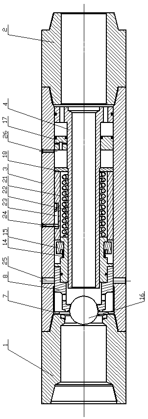
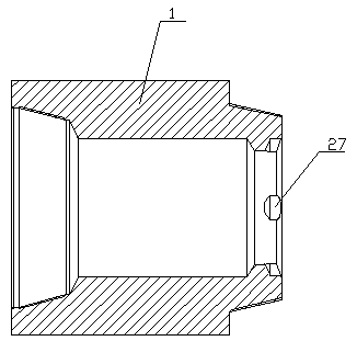
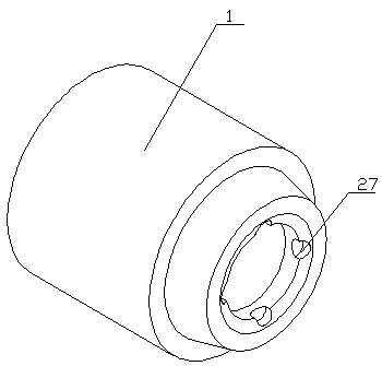
[0030] The continuous cycle valve includes an upper joint 1 , a lower joint 2 , a housing 3 and a valve core shaft 4 . One end of the housing 3 is threaded with an upper joint 1 , and the other end of the housing 3 is threaded with a lower joint 2 ; the housing 3 between the upper joint 1 and the lower joint 2 is provided with a spool shaft 4 . The spool shaft 4 is a variable diameter body, and one end of the spool shaft 4 is provided with a flange 5 , and through holes 6 are evenly distributed on the circumference of the flange 5 . The other end of the valve core shaft 4 is sleeved with a valve piston 8 through a retaining ring A7.

[0031] The valve piston 8 is composed of an upper valve body 9 and a lower valve body 10 , the upper valve body 9 and the lower valve body 10 are fitted together, and a sealing ring is arranged between the upper valve body 9 and the lower valve body 10 . The upper valve body 9 is provided with an arc-shaped switch ball port 11, and valve piston ...


PUM


Abstract

The invention relates to a circulating valve, in particular to a continuous circulating valve. The continuous circulating valve comprises an upper connector, a lower connector, a shell and a valve mandrel. The upper connector is installed at one end of the shell in a threaded mode, and the lower connector is installed at the other end of the shell in a threaded mode. The valve mandrel is arranged in the portion, between the upper connector and the lower connector, of the shell. A flange is arranged at one end of the valve mandrel. The other end of the valve mandrel is sleeved with a valve piston through a check ring A. The continuous circulating valve is simple in structure and good in practicability, working fluid can be supplied to a well bottom rapidly and continuously under the non trip situation, the drilling efficiency can be effectively improved while downhole accidents are prevented, and the problems that the nonworking time is long due to trip and replacement of a non-continuous circulating valve, consequentially the drilling efficiency is reduced, and serious economic loss is caused are solved. The continuous circulating valve is particularly suitable for the operation of well drilling, well completion, oil well maintenance, well flushing, salvage, packer setting and the like.

Description

technical field [0001] The invention relates to a circulation valve, in particular to a continuous circulation valve. Background technique [0002] The petroleum industry is a high-risk industry, and the safe production of oil wells is of great significance. The blowout and stuck accident is the most complicated and serious accident in petroleum exploration and development, and it is also one of the most important factors affecting the safe production of oil wells. harm. In order to prevent the occurrence of accidents such as leak leakage and collapse, continuous circulation valves are widely used in operations such as drilling, well completion, oil well maintenance, well washing, salvage, and packer setting. However, the current continuous circulation valves are limited by the number of cycles Due to the limitation of drilling and replacement of non-continuous circulation valves, long non-working time is caused, which reduces the drilling timeliness and causes serious eco...

Claims


Application Information

Patent Timeline
Patent Type & Authority Patents(China)
IPC IPC(8): E21B21/10E21B34/06
CPCE21B21/10E21B21/103E21B34/06E21B2200/04
Inventor 刘少胡管锋吴晗万继方吴霁薇
Owner HUBEI HONGCHENG GENERAL MACHINERY
Why Eureka
Try Eureka