Improvement structure of tee joint pipe assembly in tunnel crosswalk

A technology of three-way joints and assemblies, applied in tunnels, tunnel linings, shaft equipment, etc., can solve problems such as unsafe and reliable, and achieve the effect of ensuring safety and reliability, reducing service life, and preventing early cracks and water leakage accidents.

Active Publication Date: 2019-04-23
吴镇
View PDF10 Cites 0 Cited by
  • Summary
  • Abstract
  • Description
  • Claims
  • Application Information

AI Technical Summary

Problems solved by technology

Due to the complex geological structure of the seabed and the area near the earthquake zone, in addition to encountering faults and other 6 kinds of unfavorable geological structures during tunnel construction, we can use a number of ductile iron composite wall plate segments that we have proposed to improve the bearing capacity and ensure safety. In addition to the reliability of the quality, at the same time, the joints between the two main tunnels and the intermediate service tunnel should be subject to tens of thousands of train wheel rolling vibrations every day, resulting in fatigue damage. Preventive and countermeasures should be carefully studied and solved, especially as a subsea high-speed rail tunnel. A set of 30-meter tunnel crossways connected to both sides of the service tunnel must be set up at a distance of 80 meters. The three-way joint pipe is the most severely damaged part due to continuous cyclic vibration and long-term fatigue damage. It is obvious that the brittle material concrete members used in the past are used as crossways. It is extremely unsafe and reliable to connect the two ends of the tee joint pipe

Method used


Image

  • Improvement structure of tee joint pipe assembly in tunnel crosswalk
  • Improvement structure of tee joint pipe assembly in tunnel crosswalk
  • Improvement structure of tee joint pipe assembly in tunnel crosswalk

Examples


Embodiment 1

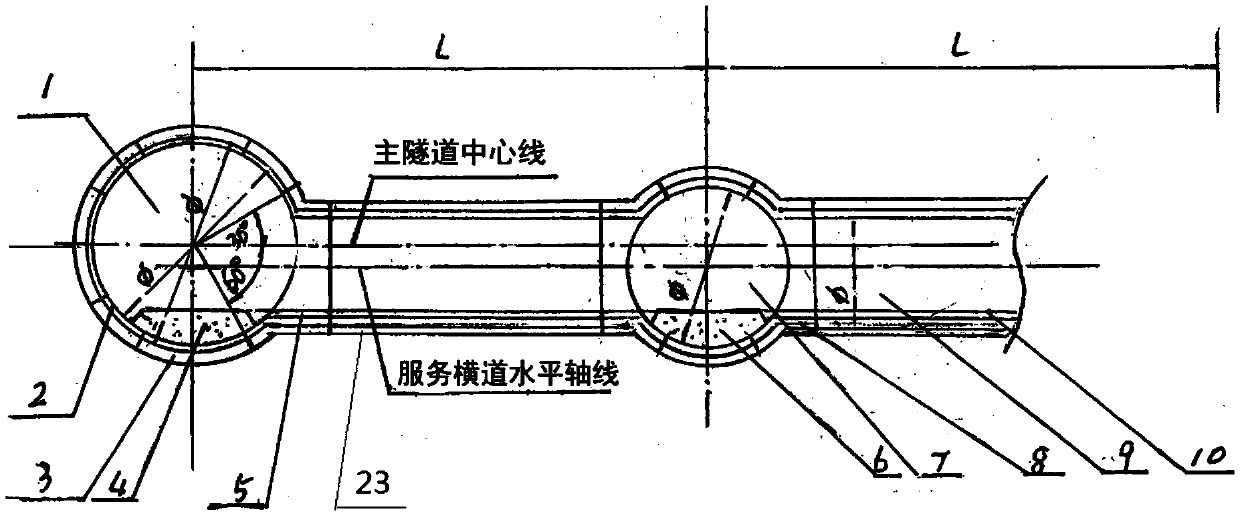
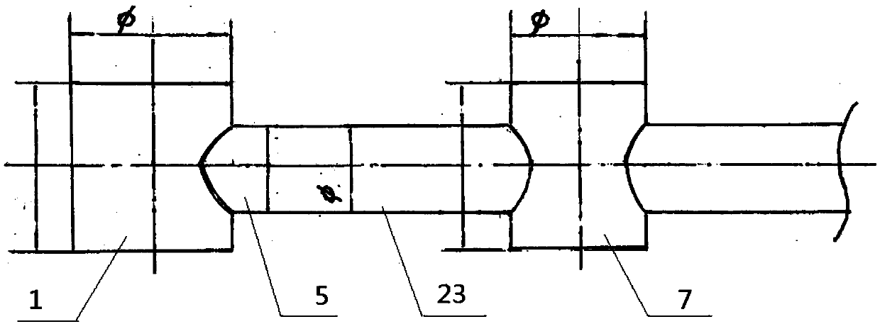
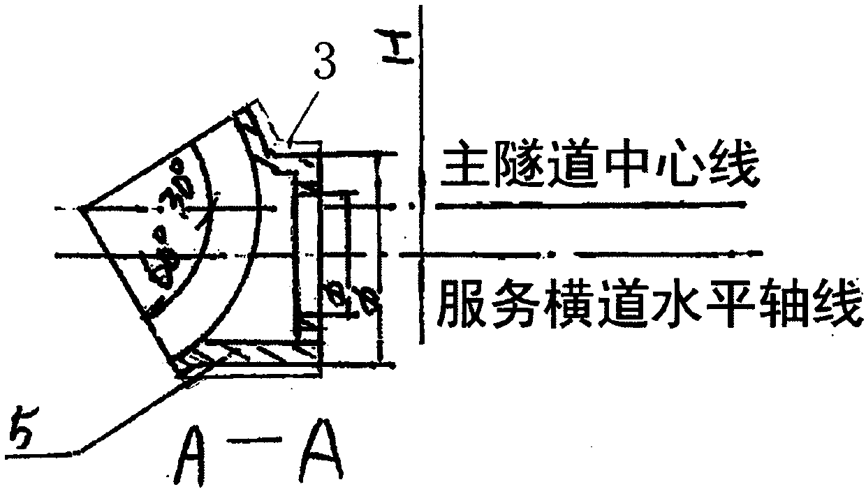
[0037] Such as Figure 1-Figure 9 As shown, the tunnel crosswalk tee joint pipe assembly in this embodiment mainly includes: main tunnel 1, ductile iron frame 2, concrete layer 3, main tunnel subgrade 4, large tee joint pipe 5, service tunnel subgrade 6, service tunnel 7. Small three-way joint pipe 8, transverse pipe gallery 9, connecting transverse road surface 10, stiffener plate 11, positioning shear sleeve 12, radial connecting hole 13, radial frame 14, axial connecting hole 15, sealing groove 16 , Axial frame 17, reinforced grid truss 18, bolt 19, service crossway 23 (such as: cross-section is an elliptical service crossway), etc., the specific structure is as follows:

[0038] A service crosswalk 23 is set between the main tunnel 1 and the service tunnel 7, and the service crosswalk 23 and the main tunnel 1 are connected by a large three-way joint pipe 5. One side of the service tunnel 7 is connected by a small three-way joint pipe 8, and the small three-way joint pipe ...

Embodiment 2

[0045] The difference from Example 1 is:

[0046] Such as Figure 10-Figure 12 As shown, the tunnel crosswalk tee joint pipe assembly in this embodiment mainly includes: main tunnel 1, ductile iron frame 2, concrete layer 3, main tunnel subgrade 4, large tee joint pipe 5, service tunnel subgrade 6, service tunnel 7. Small three-way joint pipe 8, cross passage pipe gallery 9, connecting cross road surface 10, oval service cross road 20, etc. The specific structure is as follows:

[0047] An oval-shaped service crosswalk 20 is set between the main tunnel 1 and the service tunnel 7, and the oval-shaped service crosswalk 20 and the main tunnel 1 are connected and matched through the large three-way joint pipe 5, and the two sides of the service tunnel 7 are respectively connected with the small three-way joint pipe 8 , the oval service crossway 20 and one side of the service tunnel 7 are connected and matched through a small three-way joint pipe 8, and the small three-way joint p...

Embodiment 3

[0049] The difference from Example 1 is:

[0050] Such as Figure 13 As shown, a service crosswalk 23 (such as a service crosswalk with an elliptical cross-section) is set between the two main tunnels 1 and the service tunnel 7, and the service crosswalk 23 and the main tunnel 1 are connected by a large three-way joint pipe, and the service tunnel 7 The two sides are respectively connected with the small three-way joint pipe, the service crosswalk 23 and the service tunnel 7 are connected through the small three-way joint pipe, and the evacuation passage 22 is set in the service tunnel 7 . In addition, the two main tunnels 1 communicate with the service tunnel 7 through a decompression channel 21 .

[0051] The present invention improves the cross-section (circular tube-shaped cross-section) of the channel tunnel into an elliptical vertical structure scheme. Because the construction length of the cross-channels on both sides is only more than 20 meters, it can only be constru...


PUM


Abstract

The invention relates to the field of intersecting reliability fixation of a connecting passageway of a main tunnel and a service tunnel in underground important infrastructure projects and projects such as various tunnels and city underground pipe galleries, in particular to a modified structure of a tunnel transverse way thee-joint joint pipe composite member. The tunnel transverse way thee-joint joint pipe composite member comprises a full-ball iron wall plate or a ball iron-concrete composite wall board (pipe piece), a thee-joint joint pipe, a positioning shearing-resistance sleeve, a plastic sealing ring, an oval service transverse way and the like. All the members are connected and installed to form the large tunnel transverse way thee-joint joint pipe composite member and the transverse way modified structure. The modified structure of the tunnel transverse way thee-joint joint pipe composite member is mainly suitable for reliability fixation of thee-joint joint pipes connected and communicated between various tunnels (particularly subsea tunnels) and service tunnels and thee-joint joint pipes on the joint portions of spare maintaining and emergency passageways of land high-speed railway tunnels, and the strength and tightness of connecting structures on the joints of the main tunnels and the service tunnels can be effectively improved.

Description

technical field [0001] The invention relates to the field of reliable fixation of connecting channels between main tunnels and service tunnels of important underground infrastructure projects, various tunnels and urban underground pipe corridors, and specifically relates to an improved structure of a tunnel crossway tee joint pipe assembly. Background technique [0002] At present, the structural layout of domestic land and submarine long-distance tunnels basically adopts the "two roads and one service" construction mode, which creates a very reasonable and effective engineering structure layout for tunnel decompression and ventilation or service maintenance and emergency rescue. In particular, my country's transportation construction has entered the development stage of expressways and high-speed railways, which have played an extremely important role in promoting economic development. The "13th Five-Year Plan" has included high-speed rail in the "eight vertical and eight h...

Claims


Application Information

Patent Timeline
Patent Type & Authority Patents(China)
IPC IPC(8): E21D9/14E21D11/08E21D11/38
CPCE21D9/14E21D11/08E21D11/083E21D11/385
Inventor 吴镇吴成玉吴谦吴超
Owner 吴镇
Why Eureka
Try Eureka