
Gallery separating type steel formwork trolley

A separate, steel formwork technology, applied in tunnels, tunnel linings, shaft linings, etc., can solve problems such as poor operational flexibility, inapplicability, and lack of steering functions, and achieve fast masonry speed, easy maintenance, and increased mobility. sexual effect

Inactive Publication Date: 2017-05-10
中国人民解放军63926部队
View PDF8 Cites 8 Cited by
  • Summary
  • Abstract
  • Description
  • Claims
  • Application Information

AI Technical Summary

Problems solved by technology

Therefore, the construction of the dam body grouting corridor concrete is essentially a bottom-up sequential construction. This patent is applied to corridor concrete pouring. It is different from the applicable scope of this application. The grouting corridor concrete slipform device does not Concrete pouring of the second lining for underground corridors
[0005] In addition, the grouting gallery concrete slipform device includes a trolley in the corridor, a track truss car outside the corridor, and a formwork system. Due to the existence of the track truss car outside the corridor, the concrete slipform device for the grouting gallery is not suitable for the second stage of the underground corridor. Lining concrete pouring
At the same time, because the traveling wheels of the trolley in the corridor do not have the steering function, the operation flexibility is poor, and it is not suitable for the construction of curved corridors.

Method used


Image

  • Gallery separating type steel formwork trolley
  • Gallery separating type steel formwork trolley

Examples


Embodiment

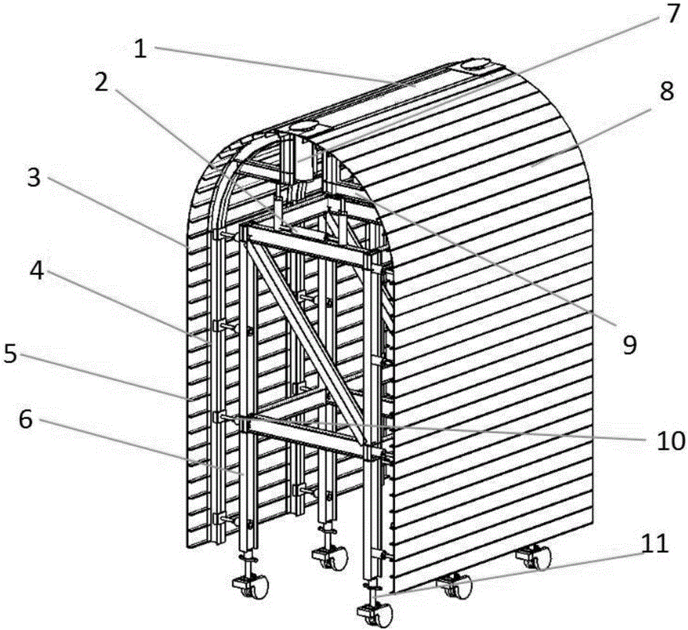
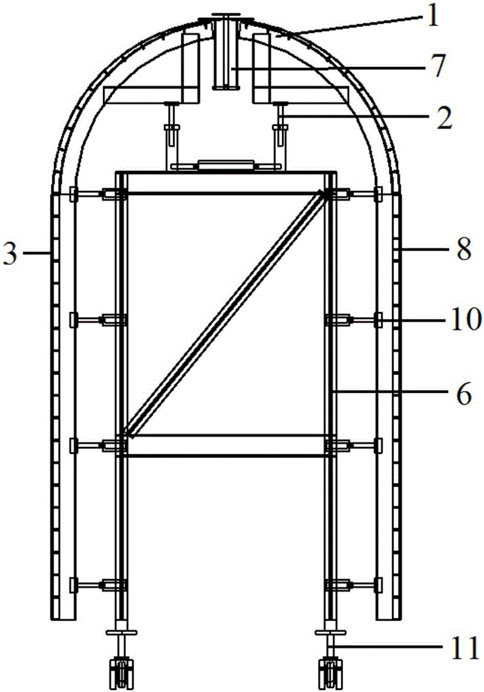
[0030] Corridor separated steel formwork trolley, its structure is as follows Figure 1-2 As shown, it includes a door frame body 6 and a top formwork 1 and a side formwork positioned on the door frame body 6. The side formwork is provided with two pieces, including a left formwork 4 and a right formwork 8, and a left formwork 4 and a right formwork 8. It is connected with the door frame body 6 through the side formwork hydraulic device 10 and the vault hydraulic device 2. The top formwork 1 is embedded in the middle of the upper part of the left formwork 4 and the right formwork 8. The top formwork 1 is equipped with a detachable grouting valve 7, and the gantry The hydraulic traveling device 11 is housed under the body 6, including rollers and a hydraulic mechanism for adjusting the height of the mast body.

[0031] The door frame body 6 adopts the I-shaped steel beams welded by steel plates to be connected by bolts. Hydraulic traveling device 11 is installed on the column ...


PUM


Abstract

The invention relates to a gallery separating type steel formwork trolley which comprises a portal body, a top formwork and two side formworks. A hydraulic traveling device is installed below the portal body; the top formwork and the two side formworks are located on the portal body; the side formworks are connected with the portal body through a side formwork hydraulic device and a vault hydraulic device; and the top formwork is embedded between the upper portions of the two side formworks. Compared with the prior art, the large steel formworks are adopted, so that the gallery separating type steel formwork trolley is simple in structure, high in strength, low in weight, and adjustable and high in lining quality; the mechanization construction degree is high, labor intensity is relieved, and work efficiency is improved; the two side formworks shrink inwards, the deformation space is large, collision is effectively reduced during demoulding and movement, and the movement speed is increased; and detachable grouting valves are arranged on the top formwork, so that the pouring quality is improved and the demoulding difficulty is reduced.

Description

technical field [0001] The invention relates to equipment for the construction of the second lining of an underground corridor, in particular to a corridor-separated steel formwork trolley. Background technique [0002] Concrete secondary lining construction is an important process in corridor construction, and the quality requirements for secondary lining construction are quite strict. The traditional two-lining construction methods include manual erection of formwork and then concrete pouring construction, and construction units designing simple construction equipment and formwork trolleys by themselves. Due to the narrow section size of the corridor, the narrow working surface, and the difficulty of construction, the first two methods have disadvantages such as high labor intensity, low degree of mechanization, slow construction progress, poor construction safety, and poor surface quality after construction. [0003] With the rapid development of the national economy and...

Claims


Application Information

Patent Timeline
Patent Type & Authority Applications(China)
IPC IPC(8): E21D11/10
CPCE21D11/102
Inventor 杨晓明郭云峰张健郭志安陈志伟高权于龙飞
Owner 中国人民解放军63926部队
Learn More