Combustion chamber of liquid rocket engine

A liquid rocket and engine technology, applied in rocket engine devices, machines/engines, mechanical equipment, etc., can solve the problems of difficult molding, long molding cycle, high cost, simple structure and molding process, short manufacturing cycle, and high cost. low cost effect

Inactive Publication Date: 2017-05-10
THE GENERAL DESIGNING INST OF HUBEI SPACE TECH ACAD
View PDF7 Cites 21 Cited by
  • Summary
  • Abstract
  • Description
  • Claims
  • Application Information

AI Technical Summary

Problems solved by technology

However, this kind of structure is complex and difficult to form. There is a closed channel between the inner and outer walls. Special processes such as brazing, diffusion welding or electroforming must be used. There are special requirements for material grades, and the forming cycle is long, costly and reliable. It is difficult to guarantee, and it is difficult to repair once a problem occurs afte

Method used


Image

  • Combustion chamber of liquid rocket engine
  • Combustion chamber of liquid rocket engine
  • Combustion chamber of liquid rocket engine

Examples


Example Embodiment

[0025] In order to make the objectives, technical solutions and advantages of the present invention clearer, the following further describes the present invention in detail with reference to the accompanying drawings and embodiments. It should be understood that the specific embodiments described herein are only used to explain the present invention, but not to limit the present invention. In addition, the technical features involved in the various embodiments of the present invention described below can be combined with each other as long as they do not conflict with each other.

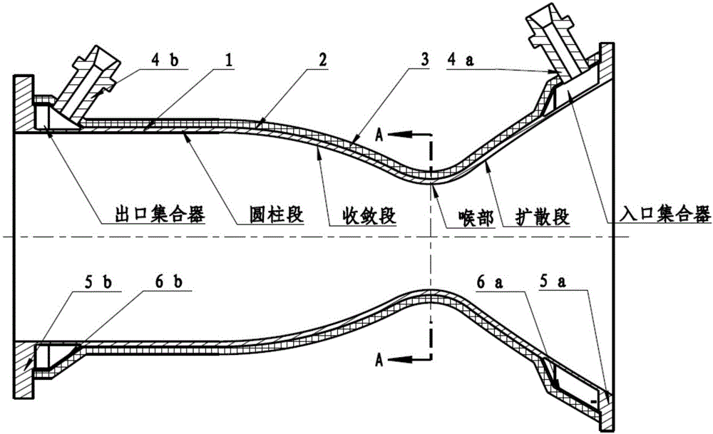
[0026] In order to solve the problems of complex molding process, high cost and harsh material requirements of the liquid rocket engine combustion chamber, the present invention proposes a liquid rocket engine combustion chamber structure using a non-metal outer wall. The inner wall of the structure adopts metal materials, and the material grade is not limited by the molding process, while the outer wa...


PUM


Abstract

The invention discloses a combustion chamber of a liquid rocket engine. The combustion chamber comprises a metal inner wall, an adhesion layer, a non-metal outer wall, a propellant inlet connector, a propellant outlet connector, a rear-end flange, a front-end flange, a tail-end bearing plate and a front-end bearing plate, wherein the non-metal outer wall and the metal inner wall form one piece through the adhesion layer; a plurality of cooling grooves which are arranged in the peripheral direction are formed in the outer surface of the metal inner wall; the front-end bearing plate and the tail-end bearing plate form an outlet collector and an inlet collector which are in the shape of an annular cavity respectively with the front-end outer wall surface and the tail-end outer wall surface of the metal outer wall respectively; the front-end flange and the rear-end flange are fixed to the front-end bearing plate and the tail-end bearing plate respectively; the outlet collector and the inlet collector are made to form a closed cavity; and the propellant inlet connector and the propellant outlet connector are connected with the inlet collector and the outlet collector respectively. The combustion chamber disclosed by the invention has the advantages of being simple in structure and forming process, convenient to operate, low in manufacturing cost and short in manufacturing period.

Description

technical field [0001] The invention belongs to the field of liquid rocket engine combustion chambers, and more particularly relates to a liquid rocket engine combustion chamber using a non-metal outer wall. Background technique [0002] The combustion chamber is an important component of the liquid rocket engine, which generates all or most of the thrust of the liquid rocket engine. The liquid propellant enters the combustion chamber through the injector, completes the process of atomization, mixing and combustion, generates high-temperature and high-pressure gas, and converts the chemical energy of the propellant into heat energy. The gas converts heat energy into kinetic energy in the nozzle, and is discharged from the outlet section of the nozzle at a high speed to generate engine thrust. [0003] In the combustion chamber of a liquid rocket engine, a large number of propellant components are burned in a short period of time under high temperature (3000K-4000K) and high...

Claims


Application Information

Patent Timeline
IPC IPC(8): F02K9/62F02K9/64
CPCF02K9/62F02K9/64
Inventor 王涛峰刘洋刘章龙司学龙高列义柳青于泉
Owner THE GENERAL DESIGNING INST OF HUBEI SPACE TECH ACAD
Why Eureka
Try Eureka