Pressure stabilizing pump

A technology of a voltage stabilizer pump and a pump body, applied in the field of voltage stabilizer pumps, can solve the problems of complex structure, the influence of implanted electronic equipment, and the inability to output continuous and stable pressure.

Inactive Publication Date: 2017-05-10
罗凤玲
View PDF5 Cites 1 Cited by
  • Summary
  • Abstract
  • Description
  • Claims
  • Application Information

AI Technical Summary

Problems solved by technology

[0002] In the application of industrial equipment and medical equipment, pump devices are commonly used to provide continuous pressure output. At present, commonly used pump devices include single pump body and double pump body, but the common single pump body can only perform pulse pressure during operation. output, unable to output continuous and stable pressure; and using a single pump body to install an accumulator to maintain pressure stability increases the cost of equipment; common double pump devices are independent double pumps, which take up a lot of space; and double pump switching It is realized by devices such as electromagnetic control valves, which have complex structures and high costs; moreover, when these pump devices are used in medical equipment, the devices such as accumulators and electromagnetic control valves are not easy to be sterilized, and it is difficult to meet the requirements of medical aseptic conditions. The requirements of internationalization, the electromagnetic control part included may also have an impact on the patient's implanted electronic equipment

Method used


Image

  • Pressure stabilizing pump
  • Pressure stabilizing pump
  • Pressure stabilizing pump

Examples


Embodiment 1

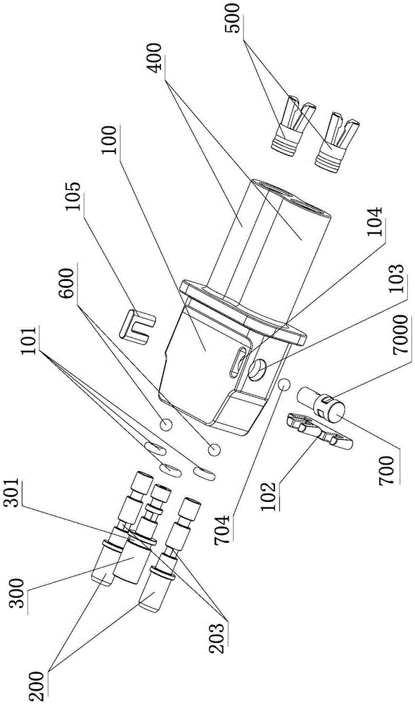
[0083] The pressure stabilizing pump described in the invention application includes a pump body, the pump body is provided with more than two input pipes, more than one output pipe and more than two piston cylinders, and the number of input pipes and piston cylinders is equal and connected in one-to-one correspondence , a one-way valve that can only close the input pipe is provided in the inlet passage of the input pipe and the piston cylinder, and each piston cylinder communicates with the output pipe through its own outlet passage, and there is a valve between the output pipe and the piston cylinder that can be closed alternately. Reversing valve for either outlet channel.

[0084] Such as figure 1 Shown is the double pump structure of the application embodiment of the present invention, including the pump body 100, the number of input pipes 200 is two, one output pipe 300, and the number of piston cylinders 400 is two, and the piston cylinder 400 can be loaded with pistons...

Embodiment 2

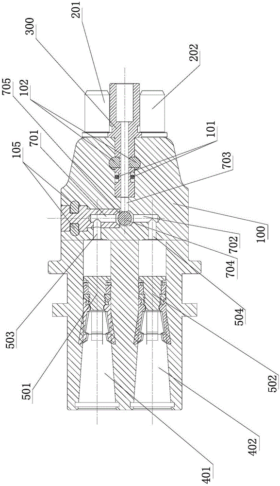
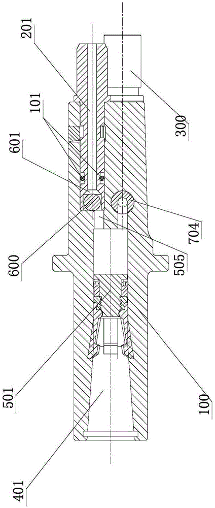
[0086] figure 2 and image 3 It shows a structural schematic diagram of different cross-sections of another embodiment of the present application, figure 2 The position and connection relationship between the piston cylinder, the reversing valve and the output pipe are specifically shown in the figure. In this embodiment, there are two piston cylinders, the first piston cylinder 401 and the second piston cylinder 402. A piston 501 and a second piston 502, the first piston cylinder 401 communicates with the first input passage 701 of the reversing valve through the first outlet passage 503 of the first piston cylinder, and the second piston cylinder 402 communicates with the first input passage 701 of the reversing valve through the second piston cylinder 402. The outlet passage 504 communicates with the second input passage 702 of the reversing valve, and the reversing valve includes a lumen 705, which communicates with the output pipe 300 through the output passage 703, an...

Embodiment 3

[0089] Figure 4 and Figure 5 It shows a schematic diagram of the working principle of an embodiment of the application of the present invention. As shown in the figure, the first input pipe 201 and the second input pipe 202 are respectively connected to the low-pressure fluid, the output pipe 300 is connected to the high-pressure pipeline, and the low-pressure fluid enters through the input pipe. The pump body, after being pumped and pressurized by the piston, is discharged through the output pipe at high pressure. Due to the asynchronous reciprocating motion between the pistons, and the regulation of the one-way valve and the reversing valve, a stable high-pressure output is formed.

[0090] Specifically, when the first piston 501 is pushed forward, the inner cavity of the first piston cylinder 401 generates high pressure, the corresponding one-way valve closes the first input pipe 201, and the reversing valve opens the connection between the first piston cylinder 401 and t...


PUM


Abstract

The invention provides a pressure stabilizing pump aiming at shortcomings of a pressure stabilizing pump used at present. The pressure stabilizing pump can output continuous and stable high pressure, is small in size and facilitates asepsis treatment. The pressure stabilizing pump comprises a pump body which is provided with two or more input pipes, one or more output pipes and two or more piston cylinders. The input pipes and the piston cylinders are equal in number and communicate in a one-to-one corresponding manner. One-way valves which can only close the input pipes are arranged in inlet channels of the input pipes and inlet channels of the piston cylinders. Each piston cylinder communicates with the corresponding output pipe through the respective outlet channel. Reversing valves capable of closing any outlet channel alternately are arranged between the output pipes and the piston cylinders. A piston and a piston rod driving the piston to move are arranged in each piston cylinder.

Description

technical field [0001] The application of the present invention relates to a pump, especially a pump capable of maintaining a stable output pressure, which can be applied to medical equipment. Background technique [0002] In the application of industrial equipment and medical equipment, pump devices are commonly used to provide continuous pressure output. At present, commonly used pump devices include single pump body and double pump body, but the common single pump body can only perform pulse pressure during operation. output, unable to output continuous and stable pressure; and using a single pump body to install an accumulator to maintain pressure stability increases the cost of equipment; common double pump devices are independent double pumps, which take up a lot of space; and double pump switching It is realized by devices such as electromagnetic control valves, which have complex structures and high costs; moreover, when these pump devices are used in medical equipme...

Claims


Application Information

Patent Timeline
Patent Type & Authority Applications(China)
IPC IPC(8): F04B1/02F04B53/16F04B53/10F04B53/14F04B53/22
CPCF04B1/02F04B53/10F04B53/1002F04B53/14F04B53/16F04B53/22
Inventor 罗凤玲
Owner 罗凤玲
Why Eureka
Try Eureka