A Precisely Adjustable Gas Flow Nozzle

A gas flow and nozzle technology, which is applied in the direction of valve devices, safety valves, and functional valve types, can solve the problems of inability to adjust air flow in a large range, low flow control accuracy, and limited flow working conditions, and achieve simplified structure. and control, simplify the sealing mechanism, and realize the effect of automatic adjustment

Active Publication Date: 2020-05-12
CHINA ACAD OF AEROSPACE AERODYNAMICS
View PDF6 Cites 0 Cited by
  • Summary
  • Abstract
  • Description
  • Claims
  • Application Information

AI Technical Summary

Problems solved by technology

[0003] Direct adjustment generally uses a flow control valve to directly use the flow meter acquisition signal as a feedback signal, generate a control signal through an intelligent PID control algorithm, and drive the control valve to perform flow adjustment. This method has a relatively simple system structure, but is limited by the accuracy of the existing gas flow meter and the valve Influenced by the size of front and rear airflow disturbances, the accuracy deviation is more than 5%, and the flow control accuracy is not high
[0004] The other is the throttling method, which is a multi-pipe group with a pressure reducing valve and a throttle orifice. According to the combination of pipelines, the pressure reducing valve reduces the pressure of the gas source to the required pressure. , to precisely control the air flow, the control system of this method is relatively simple, and the air flow control accuracy is high, but the equipment structure is relatively complicated, the working conditions that can adjust the flow are limited, and it is impossible to adjust the air flow in a large range

Method used


Image

  • A Precisely Adjustable Gas Flow Nozzle
  • A Precisely Adjustable Gas Flow Nozzle
  • A Precisely Adjustable Gas Flow Nozzle

Examples


Embodiment Construction

[0025] Below in conjunction with accompanying drawing and specific embodiment the present invention is described in further detail:

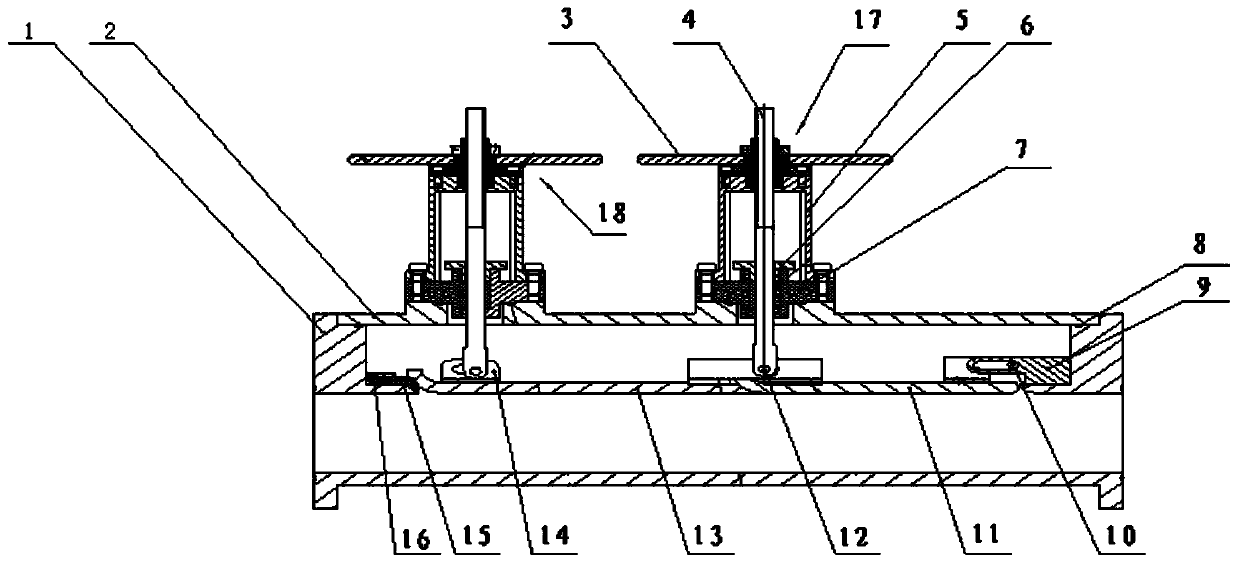
[0026] Such as figure 1 Shown is a schematic diagram of an adjustable flow nozzle. It can be seen from the figure that a precise adjustable gas flow nozzle includes a device casing 1, an upper end cover 2, a first mounting support 9, a front adjustment sealing plate 15, and a sealing gasket 16 , the spout adjustment mechanism 17 and the compression sealing mechanism 18; wherein, the equipment casing 1 is located at the bottom; the top of the equipment casing 1 is provided with a stepped groove; the upper end cover 2 is fixedly installed in the equipment casing 1 stepped groove On the outer edge of the device housing 1 and at the same level as the upper surface of the device housing 1; the contact position between the device housing 1 and the upper end cover 2 is fixedly installed with a sealing ring 8, which is made of polytetrafluoroethylene ma...


PUM


Abstract

The invention provides a precise and adjustable gas flow spray pipe and relates to the field of air flow adjustment. The precise and adjustable gas flow spray pipe comprises an equipment shell, an upper end cover, a first installation support, a front adjustment sealing plate, a sealing pad, a spray nozzle adjustment mechanism and a pressing and sealing mechanism. The upper end cover is fixedly installed on the outer edge of a ladder-shaped groove of the equipment shell; the spray nozzle adjustment mechanism is fixedly installed in the middle of the top of the upper end cover; the pressing and sealing mechanism is fixedly installed at one end of the top of the upper end cover; the end, close to the pressing and sealing mechanism, of the bottom of the ladder-shaped groove of the equipment shell, and the top end is fixedly provided with the sealing pad; and one end of the bottom of the ladder-shaped groove of the equipment shell is provided with the first installation support. By means of the precise and adjustable gas flow spray pipe, the problem of precise control over gas flow is solved, a high-precision flow adjustable spray pipe meets the requirement for precise adjustment on wide-range gas flow and flow velocity, the problem that a pore plate, a Venturi spray nozzle and other flow adjustment devices can only correspond to one flow parameter under the situation that the pressure is unchanged is solved, and a novel device is provided for pipe gas flow adjustment.

Description

technical field [0001] The invention relates to the field of air flow regulation, in particular to a precisely adjustable gas flow nozzle. Background technique [0002] At present, the commonly used air flow adjustment schemes can be divided into two categories: one is direct adjustment, and the other is throttling adjustment. [0003] Direct adjustment generally uses a flow control valve to directly use the flow meter acquisition signal as a feedback signal, generate a control signal through an intelligent PID control algorithm, and drive the control valve to perform flow adjustment. This method has a relatively simple system structure, but is limited by the accuracy of the existing gas flow meter and the valve Influenced by the size of front and rear airflow disturbances, the accuracy deviation is more than 5%, and the flow control accuracy is not high. [0004] The other is the throttling method, which is a multi-pipe group with a pressure reducing valve and a throttle o...

Claims


Application Information

Patent Timeline
Patent Type & Authority Patents(China)
IPC IPC(8): F16K3/06F16K3/314F16K17/20
CPCF16K3/06F16K3/314F16K17/20
Inventor 张业华穆东波刘怀印
Owner CHINA ACAD OF AEROSPACE AERODYNAMICS
Why Eureka
Try Eureka