Pipeline reversing valve

A reversing valve and pipeline technology, which is applied to multi-port valves, valve devices, engine components, etc., can solve the problems of easy fluctuation in the switching process, complicated valve cavity manufacturing process, limited industrial application, etc., and achieves simple and practical structure. The effect of shortening the movement distance and not easy to fluctuate

Inactive Publication Date: 2017-05-10
罗凤玲
View PDF9 Cites 5 Cited by
  • Summary
  • Abstract
  • Description
  • Claims
  • Application Information

AI Technical Summary

Problems solved by technology

However, the manufacturing process of the semi-cylindrical valve cavity is complicated, and when the spherical valve disc is required to reciprocate quickly in the semi-cylindrical valve cavity to achieve fast reversing, the motion cycle is long, and fluctuations are likely to occur during the switching process.
Therefore, the existing technology cannot be used to realize the long-term and continuous fast switching function, and is only used for switching during disassembly, and is limited to industrial applications.

Method used


Image

  • Pipeline reversing valve
  • Pipeline reversing valve
  • Pipeline reversing valve

Examples


Embodiment 1

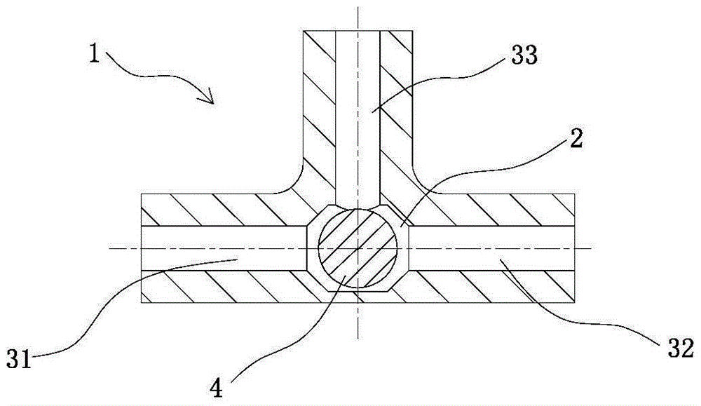
[0020] Such as figure 1 As shown, it is a cross-sectional structure diagram of an embodiment of the application of the present invention. In this embodiment, the pipeline reversing valve includes a valve body 1, the valve body 1 has a lumen 2, and the valve body 1 also has a lumen 2. The connected first inlet passage 31, second inlet passage 32, and outlet passage 33 are provided with a spool 4 that can alternately close the first inlet passage 31 or the second inlet passage 32 and keep the outlet passage open 33 in the lumen 2 , in this embodiment, the spool 4 is a solid ball, the first inlet passage 31 and the second inlet passage 32 are on the same line as the lumen 2, and the outlet passage 33 is connected to the first inlet passage 31 and the second inlet passage. Channel 32 is vertical.

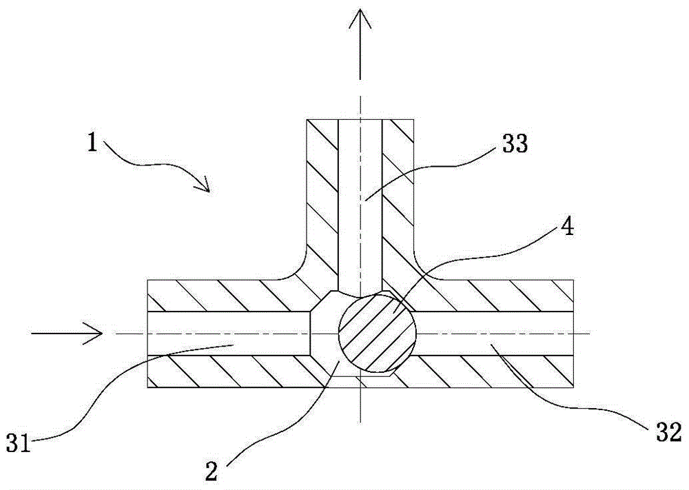
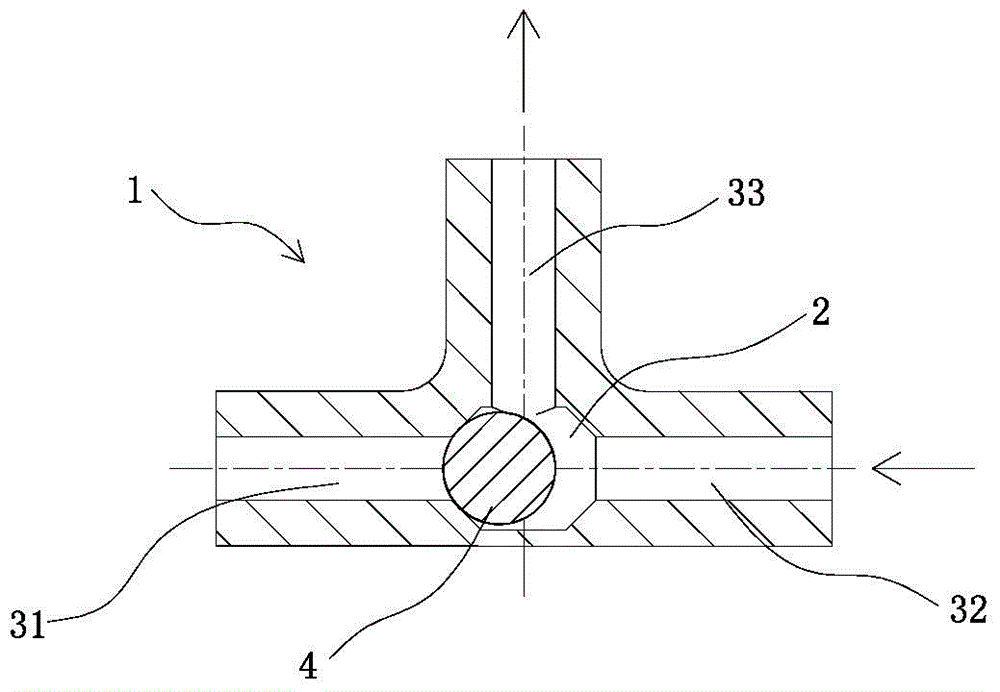
[0021] figure 2 and 3 Then the working principle of this embodiment is shown, when the first inlet passage 31 has water flow to enter, pushes the spool 4 to move, blocks the entran...

Embodiment 2

[0023] Such as Figure 4 As shown, it is a cross-sectional structure diagram of an embodiment of the application of the present invention. In this embodiment, the pipeline reversing valve includes a valve body 1, the valve body 1 has a lumen 2, and the valve body 1 also has a lumen 2. The connected first inlet channel 31 and the second inlet channel 32, and the outlet channel 33, the outlet channel 33 is not perpendicular to the first inlet channel 31 and the second inlet channel 32, but outward to one side, in the lumen 2 is provided with a The spool 4 alternately closes the first inlet passage 31 or the second inlet passage 32 and keeps the outlet passage open 33 . In this embodiment, the spool 4 is a hollow sphere.

[0024] Figure 5 and 6 Then the working principle of this embodiment is shown, when the first inlet passage 31 has water flow to enter, pushes the spool 4 to move, blocks the entrance of the second inlet passage 32, closes the second inlet passage 32, and the...

Embodiment 3 7

[0026] Figure 7-11 The structures of different embodiments are shown. In each embodiment, the outlet channel 33 is perpendicular to the inlet channel. It should be clear that the outlet channel may not be perpendicular to the inlet channel. The difference between the various embodiments is that the structure and shape of the spool 4 are different. Figure 7 In the embodiment, the spool 4 is a hollow sphere; Figure 8 In the embodiment, the spool 4 is a solid cylinder; Figure 9 In the embodiment, the valve core 4 is a hollow cylinder; Figure 10 and Figure 11 The spool 4 in the embodiment is irregular and can be solid or hollow, or semi-solid, as long as it has a contact surface that can close the first inlet passage 31 and the second inlet passage 32 .

[0027] In the pipeline reversing valve described in the application of the present invention, the valve core is located in the lumen, and under the alternating impact of water flow (or air flow) in different inlet chann...


PUM


Abstract

The invention provides a pipeline reversing valve which comprises a valve body with a tubular cavity; the valve body is provided with two or more inlet channels and one or more outlet channels, which communicate with the tubular cavity; the outlet channels can be perpendicular to the inlet channels, and also can be not perpendicular to the inlet channels; a vale element capable of alternatively sealing at least one inlet channel to keep the outlet channels open is arranged in the tubular cavity; the valve element is solid or hollow or semi-solid, and comprises a ball body, a column body or an irregular body which can alternatively seal the contact surface of any inlet channel. The pipeline reversing valve is simple and practical in structure, and is convenient to produce and manufacture; and moreover, the sealed valve body is in reciprocating motion on one plane, a motion distance is reduced, and fluctuation is not easily generated in a switching process, so that the pipeline reversing valve is especially suitable for switching pipelines in a medical pump.

Description

technical field [0001] The application of the present invention relates to a valve, especially a valve for pipeline reversing, which can be applied to medical equipment. Background technique [0002] At present, in order to realize the circulation, cut-off and reversing of the pipeline, it is often necessary to install a directional control reversing valve in the pipeline. Reversing valves are generally divided into manual reversing valves, electromagnetic reversing valves, electro-hydraulic reversing valves, etc. The manual reversing valve requires real-time control by personnel, which is time-consuming and laborious, and the degree of automation is not high; the electromagnetic reversing valve uses the electromagnetic suction to push the valve core to change the working position of the valve, and the electro-hydraulic reversing valve is an electromagnetic reversing valve and a hydraulic control reversing valve. Combination of directional valves; these valves need to be co...

Claims


Application Information

Patent Timeline
Patent Type & Authority Applications(China)
IPC IPC(8): F16K11/044
CPCF16K11/044
Inventor 罗凤玲
Owner 罗凤玲
Why Eureka
Try Eureka