Base station air conditioner and control method thereof

A base station air conditioner and control signal technology, which is applied to the control input related to air characteristics, space heating and ventilation control input, air conditioning system, etc. It can solve problems such as equipment damage, short circuit, and poor use environment, so as to ensure normal operation , The operation process is stable and the degree of autonomy is good

Active Publication Date: 2017-05-10
QINGDAO HAIER AIR CONDITIONING ELECTRONICS CO LTD +1
7 Cites 0 Cited by

AI-Extracted Technical Summary

Problems solved by technology

This has the following problems: there are a large number of solid particles and liquid particles with a size ranging from 0.1 μm to 1000 μm in the air environment of the computer room. These solid particles and liquid particles have a strong adsorption capacity. Once they enter the cabinet or the body of the air conditioning equipment, It will be attached for a long time, which will seriously affect the heat dissipat...

Method used

During the use of the base station air conditioner, once it is found that the purification filter screen 3 needs to be replaced according to the automatic detection or manual detection mode, the operator can complete the removal of the purification filter screen 3 and the filter detection device 13 in a very short time. Pack. Similarly, when the base station air conditioner needs to change the use environment, you can choose to replace one filter or multiple filters, or change the mesh numbers of multiple filters to achieve the ideal use effect of the filter device. Since the air inlet 2 of the base station air conditioner mostly adopts a fixed cross-section to enter the air, the effect of changing the air intake air volume can also be achieved by changing the aperture and hole shape of the purification filter 3 in the filter device.
In the purifying device described in detail in the above-mentioned embodiment, the angle between the first direction D1 and the second direction D2 can be between 0 and 90 degrees, considering the material strength of the limiting assembly, it is preferred that the first direction The included angle between the first direction D1 and the second direction D2 is set to be 90 degrees. The first limiting member 4 and the second limiting member 5 can be integrally formed with the inner wall of the housing 1, or welded to the housing 1, so as to avoid the use of connecting parts such as bolts and increase the risk of problems such as corrosion.
Referring to Fig. 2 to shown in Fig. 4, same as traditional civil air conditioner in the prior art, in the running process of air conditioner, heat exchanger can form a certain amount of condensed water, so, usually in heat exchanger A water collecting tray 10 is arranged below, and through the drainage function of the water collecting tray 10 and the drain outlet opened on the water collecting tray 10, the condensed water is led out to the outdoor for discharge, so as to prevent the condensed water from causing irreversible damage to electrical equipment or other equipment in the air-conditioned room. damage. However, for base station air conditioners, the concentration of particles contained in the natural dust and artificial dust sources in the air is relatively high, and it varies greatly with time. These particles enter the interior of the air conditioner housing 1 with the air from the air inlet 2, and not only deposit and land on the electronic equipment, but also accumulate in the water collecting pan 10 along with the condensed water, and block the drainage with the condensed water discharge. mouth. The condensed water in the water collecting pan 10 overflows and flows to other positions in the housing 10 after accumulating to a certain extent, causing irreversible damage to the equipment. Since the air-conditioned room of the base station air conditioner is not always occupied, the overflowed condensed water will not be cleaned up in time. Once the condensed water overflows, it may overflow the casing and cause greater damage. In view of the above problems, this embodiment provides a base station air conditioner, which provides a protection structure on the premise of ensuring the working state requirements of the base station air conditioner. A water collecting pan 10 is arranged below the heat exchanger of the base station air conditioner. As shown in the figure, the water collecting pan 10 is surrounded by a side wall 10 - 3 , and an opening is formed on the top, and the condensed water formed by the heat exchanger enters the water collecting pan 10 from the opening and gathers. Completely different from the prior art, in this embodiment, the side wall 10-3 of the water collecting tray 10 is formed with a raised portion 10 protruding upwards from the edge of the side wall 10-3 along the extending direction of the side wall 10-3. -6, the raised portion 10-6 is integrally formed with the side wall 10-3. The raised portion 10-6 can be arranged vertically as shown in Fig. 1 and Fig. 2, or it can be in the shape of gradually retracting inward, so as to prevent the condensed water from flowing out of the water collecting tray 10 when it gathers to a certain amount. A first drainage hole 10-1 and a second drainage hole 10-2 are opened on the water collecting tray 10, wherein the first drainage hole 10-1 is opened on the raised portion 10-6, and the second drainage hole 10-2 is opened On the side wall 10-3, the opening position of the first drain hole 10-1 is higher than that of the second drain hole 10-2, and the lowest point of the first drain hole 10-1 is higher than that of the side wall 10-3. edge. Through the combination of the first drain hole 10-1 and the second drain hole 10-2, a redundant protection scheme for the blockage of the drain hole is realized. When the accumulated water in the water collection tray 10 exceeds the second drain hole 10- When the upper edge of 2 continues to rise, the first drainage hole 10-1 can timely drain the accumulated condensed water outwards, so as to avoid damaging other electronic equipments by flowing into the casing 1 . The diameter of the first drainage hole 10-1 is preferably smaller than that of the second drainage hole 10-2, so as to divert the condensed water during a normal maintenance period.
The base station air conditioner provided in this embodiment is especially designed to operate under severe conditions and to meet the requirements of high air quality. Through the cooperation of the filter device and the refrigerant cycle, the temperature environment and humidity in the air-conditioned room can be realized. The overall adjustment of the air quality of the environment, through the design of the secondary drainage structure, prevents the condensed water from overflowing due to the blockage of the second drainage space when no one is checking, causing irreversible damage to the equipment. At the same time, through the specially designed structure of the filter device, on the one hand, the reserved space required for replacing the filter device is effectively reduced, on the other hand, the installation and disassembly process of the f...

Abstract

The invention provides a base station air conditioner. The base station air conditioner comprises a heat exchanger, a compressor, a cooling agent cycle and a water pan. The cooling agent cycle is formed between the heat exchanger and the compressor, the water pan is arranged below the heat exchanger and comprises a sidewall and a protrusion portion, the protrusion portion extends out of the edge of the sidewall upwardly along the extension direction of the sidewall and is integrally formed with the sidewall, the water pan is provided with a first water drainage hole and a second water drainage hole, the first water drainage hole is formed in the protrusion portion, the second water drainage hole is formed in the sidewall, and the lowest point of the first water drainage hole is higher than the edge of the sidewall. The invention further discloses a control method of the base station air conditioner. The base station air conditioner has the advantages that with the aid of a redundancy protecting structure, condensed water formed by the heat exchanger is prevented from overflowing due to dust accumulation to cause irreversible damage to equipment and a room where the air conditioner is located; the base station air conditioner is reliable in structure and good in use effect.

Application Domain

Mechanical apparatusCondensate prevention +6

Technology Topic

RefrigerantCondensed water +2

Image

  • Base station air conditioner and control method thereof
  • Base station air conditioner and control method thereof
  • Base station air conditioner and control method thereof

Examples

  • Experimental program(1)

Example Embodiment

[0036] In order to make the objectives, technical solutions, and advantages of the embodiments of the present invention clearer, the technical solutions in the embodiments of the present invention will be described clearly and completely in conjunction with the accompanying drawings in the embodiments of the present invention. Obviously, the described embodiments It is a part of the embodiments of the present invention, not all the embodiments. Based on the embodiments of the present invention, all other embodiments obtained by those of ordinary skill in the art without creative work shall fall within the protection scope of the present invention.
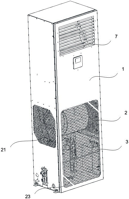
[0037] See figure 1 Shown is a schematic structural diagram of an embodiment of the base station air conditioner disclosed in the present invention. In this embodiment, the defined base station air conditioner is used in base stations set up in computer rooms, in the wild, in the desert, outskirts or similar areas, working under stricter conditions, and at the same time has higher requirements for the air quality of the air-conditioned room Regional air conditioning device. Compared with traditional civil air conditioners, the application fields of the base station air conditioners disclosed in this embodiment have the following particularities. One is that the application occasions may be adjacent to railways, docks, airports or chemical plants and other areas where a large amount of volatile dust and toxic and harmful gases are emitted; The second is that the air quality required by the room itself is higher than that of civil occasions; the third is that it needs to operate under continuous long-term working conditions. Based on the above three special requirements and taking environmental factors into consideration, base station air conditioners are required to have four requirements for adjusting humidity, temperature, air quality, and continuous long-term work. In the base station air conditioner disclosed in this embodiment, in order to solve the above-mentioned problems, the humidity and temperature adjustment is realized by forming a refrigerant cycle between the heat exchanger and the compressor, and continuous long-term operation is realized by the cooperation of multiple redundant power supply systems. . In addition, as a prerequisite preparation to assist in ensuring long-term continuous operation, in this embodiment, the compressor is installed in the housing 1 in the air-conditioned room to protect the compressor and avoid making the compressor work under severe conditions. Work down, reduce the performance requirements of the compressor, and increase the service life of the compressor.
[0038] See Figure 2 to Figure 4 As shown, as with traditional civil air conditioners in the prior art, during the operation of the air conditioner, a certain amount of condensed water is formed in the heat exchanger. Therefore, a water collecting pan 10 is usually arranged under the heat exchanger. The drainage function of the water collecting tray 10 and the drain opening on the water collecting tray 10 leads the condensate water to be discharged outside, so as to prevent the condensate water from causing irreversible damage to electrical equipment or other equipment in the air-conditioned room. However, for base station air conditioners, the concentration of particles contained in the natural dust and artificially formed dust sources in the air is relatively high, and they vary greatly over time. These particles enter the inside of the air conditioner housing 1 with the air inlet 2 and not only deposit and land on the electronic equipment, but also accumulate in the collecting tray 10 with the condensed water, and block the drainage as the condensed water is discharged. mouth. The condensed water in the water collecting tray 10 overflows and flows to other locations in the housing 10 after being accumulated to a certain extent, causing irreversible damage to the equipment. Since the air-conditioned room of the base station air conditioner is not always in a human state, the overflowing condensate will not be cleaned up in time. Once the condensate overflows, it may overflow the shell and cause greater damage. In response to the foregoing problems, this embodiment provides a base station air conditioner, and provides a protection structure under the premise of ensuring the working state requirements of the base station air conditioner. A water collecting pan 10 is provided under the heat exchanger of the base station air conditioner. As shown in the figure, the water collecting pan 10 is surrounded by a side wall 10-3, and an opening is formed on the upper side. The condensed water formed by the heat exchanger enters the water collecting pan 10 from the opening and collects. Completely different from the prior art, in this embodiment, the side wall 10-3 of the water collecting tray 10 is formed with a protrusion 10 extending upward from the edge of the side wall 10-3 along the extending direction of the side wall 10-3. -6, the protrusion 10-6 and the side wall 10-3 are integrally formed. The raised portion 10-6 can be as figure 1 with figure 2 The vertical arrangement may also be in the form of gradually retracting slightly inward to prevent the condensed water from flowing out of the water collecting tray 10 when the condensed water collects to a certain amount. A first drainage hole 10-1 and a second drainage hole 10-2 are opened on the water collecting pan 10, wherein the first drainage hole 10-1 is opened on the protrusion 10-6, and the second drainage hole 10-2 is opened On the side wall 10-3, the opening position of the first drain hole 10-1 is higher than the opening position of the second drain hole 10-2, and the lowest point of the first drain hole 10-1 is higher than that of the side wall 10-3. edge. Through the combination of the first drainage hole 10-1 and the second drainage hole 10-2, a redundant protection scheme against the blockage of the drainage hole is realized. When the accumulated water in the sump 10 exceeds the second drainage hole 10- When the upper edge of 2 continues to rise, the first drain hole 10-1 can drain the accumulated condensate outward in time to avoid flowing into the housing 1 to damage other electronic devices. The aperture of the first drain hole 10-1 is preferably smaller than the aperture of the second drain hole 10-2, which serves as a diversion for the condensate during a normal maintenance cycle.
[0039] Since the first drainage hole 10-1 is a designed protection structure, it must be ensured that the first drainage hole 10-1 is unblocked when needed. As a preferred solution for drain hole design, a first solenoid valve 10-7 is provided at the first drain hole 10-1. When controlled by the first solenoid valve 10-7 in the normal working state, the first drain hole 10-1 is closed to prevent particles from accumulating in the first drain hole 10-1, causing the first drain hole 10-1 to be drained. It is blocked at times, and the corresponding technical effect cannot be achieved. The first drain hole 10-1 is connected to the outdoors through a first drain pipe. Also based on the strict consideration of the application environment of the base station air conditioner, in order to avoid the situation that the first drain pipe freezes and cannot be drained during the drainage process, a serpentine or spiral shape is laid on the pipe wall 10-4 of the first drain pipe. Electric heating tube. At the same time, when the first drain hole 10-1 is closed, the electric heating pipe does not work. Of course, it is also possible to lay an electric heating tube in the bottom plate of the water collecting tray 10 to achieve the effect of preventing icing as a whole.
[0040] In this embodiment, the on and off of the first drain hole 10-1 is automatically controlled by a switch level signal. When the second drainage hole 10-2 is blocked, the first drainage hole 10-1 is automatically opened to act as a drain. A sensing device can be separately provided at the second drain hole 10-2 to detect its on-off, and the working state of the second drain hole 10-2 can also be sampled by the following structure. Specifically, through the following solutions, in view of the needs of base station air conditioners that may need to be applied in areas where a large amount of volatile dust and toxic and harmful gases are required, in this embodiment, a set of purification devices are specially designed to obtain the first 2. Working status of the drain hole. Specifically, as shown in the figure, taking the indoor end as an example, an air inlet 2 is opened on the housing 1 arranged in an air-conditioned room, and the air inlet 2 extends along the housing 1 and has a fixed air inlet cross-sectional area. The purification device is arranged inside the air inlet 2. The air inlet 2 opened on the shell 1 is set on the lower side of the shell 1. During the air circulation, the air intake of the air inlet 2 is the gas processed by the base station air-conditioning in the air-conditioned room. Compared with the harsh external environment In other words, it is an available source of clean air. In order to further adjust the air quality, the purification device includes a purification filter 3, which can be made of a variety of materials, including but not limited to stainless steel, brass and other metals with continuous pore structure. Sintered metal mesh, or continuous pore structure filter material sintered with plastic or plastic powder as raw materials, etc., for the use environment of base station air conditioners, the filtration accuracy of the purification filter 3 is 0.5 μm to 100 μm.
[0041] In order to achieve a certain filtering accuracy, the mesh number of the purification filter 3 is determined. At the same time, the diameter of the second drain hole 10-2 is also determined. Therefore, when the purification filter 3 reaches a certain filtering limit, it can be determined by the proportional relationship between the two that there must be dust accumulation in the second drain hole 10-2 in a certain blocking state. Based on the above relationship, a filter detection device 13 is provided on both sides of the purification filter 3, and the filter detection device 13 can be a sensor that detects light intensity or a sensor that detects pressure. By detecting the light intensity at both ends of the purification filter 3 And pressure to determine the degree of dust accumulation on the purification filter 3. When the degree of dust accumulation on the purification filter 3 reaches the set threshold, the filter detection device 13 outputs a detection signal to the control unit 11, and the control unit 11 outputs a control signal to the first solenoid valve 10-7 to control the first solenoid valve 10. -7 is opened, so that the first drain hole 10-1 is in a ready state. The control unit 11 provided in this embodiment can be a single-chip microcomputer or a similar integrated circuit with input and output ports that can output logic signals. Receiving an analog detection signal and outputting a logic control signal is well known in the prior art, and the specific signal processing will not be further introduced here. The dust accumulation state of the purification filter 3 detected by the filter detection device 13 further obtains the use state of the second drainage hole 10-2, which can be used as a basis for the opening and closing of the first drainage hole 10-1.
[0042] For base station air conditioning equipment, the purification filter 3 will be cleaned or replaced in a fixed period. After cleaning and replacing the purification filter 3, a filter detection device 13 needs to be installed, and at the same time, the user can clean the water collecting tray 10. The filter detection device 13 detects that the degree of dust accumulation on the newly replaced purification filter 3 belongs to the initial setting range. The filter detection device 13 outputs an opposite control signal to the first solenoid valve 10-7 through the control unit to control the first solenoid valve 10-7 is closed, and the first drain hole 10-1 is in a closed state, ready for the execution of the next cycle.
[0043] For traditional air conditioning equipment or ventilation equipment, a similar purification filter 3 may also be designed. The method used is to fix the purification filter 3 to the inner wall of the housing 1 through bolts. Due to the limitation of the use environment of the base station air conditioner, the service life of the purification filter 3 is much shorter than that of the civil air conditioner, so the replacement cycle is more frequent. If the traditional bolt connection method is used, on the one hand, because the internal layout of the housing 1 is relatively compact, if the filter detection device 13 needs to be installed, it will further squeeze the available space inside the housing 1. The maintenance personnel are inside the housing 1. There is basically no place to perform replacement operations. On the other hand, if the bolts are corroded, they must be disassembled in a destructive manner, and the installation of the new filter is basically impossible, which further causes the designed redundant drainage structure to fail to work automatically; third, If the base station air conditioner is replaced with a use environment, the filter cannot be expanded, so this method is not desirable for the base station air conditioner disclosed in this embodiment. In order to overcome the above-mentioned problems, in this embodiment, a matching structure of the limit component and the purification filter 3 is designed.
[0044] See Figure 5 to Figure 12 As shown, specifically, the limiting component includes at least one set of limiting members arranged opposite to each other, which are defined as the first limiting member 4 and the second limiting member 5 for ease of description. The first end 41 of the first limiting member 4 is disposed on the inner wall of the housing 1, and the second end 42 of the first limiting member 4 extends along the first direction D1. There is an interval 43 between the first end 41 and the second end 42, and the interval 43 extends in the second direction D2. An angle is formed between the first direction D1 and the second direction D2. Correspondingly, the first end 51 of the second limiting member 5 is also arranged on the inner wall of the housing 1. Since the second limiting member 5 and the first limiting member 4 are arranged opposite to each other, the second limiting member 5 The second end 52 also extends in a direction opposite to the first direction D1, and there is also an interval 53 between the first end 51 and the second end 52 of the second limiting member 5. In this way, through the first limiting member 4 and the second limiting member 5 disposed opposite to each other, a space area limited by the second end and capable of accommodating the purification filter 3 is formed between them, which is formed at the first limit. The distance between the two spaces 43 and 53 in the positioning member 4 and the second limiting member 5 basically matches the distance from one edge to the other edge of the purification filter 3, which is sufficient to meet the installation requirements of the purification filter 3. .
[0045] For ease of description, a set of correspondingly arranged edges of the purification filter 3 is defined as the first edge 31 and the second edge 32. For a special-shaped filter, such as a circular filter, the first edge 31 and the second edge 32 are two points on a circle with the same diameter, and for an elliptical filter, they are two points on the long axis. The first edge 31 and the second edge 32 have no significant difference in structure. When installing the purification filter screen 3 through the partition area, the first edge 31 of the purification filter screen 3 is extended from the space 43 formed in the first limiting member 4 until the first edge 31 contacts the first limiting member 4 . When the first edge 31 of the purification filter 3 is in contact with the first limiting member 4, a gap 6 exists between the second end 52 of the second limiting member 5 and the second edge 32 of the purification filter 3 along the first direction D1. . The second edge 32 of the purification filter 3 moves along the second direction D2 and enters the gap 53 formed in the second limiting member 5. Under the action of the external force, the second edge 32 of the purification filter 3 is in contact with the second limiting member 5, and the first edge 31 and the first limiting member 4 are separated. Under the limiting action of the second end 42 of the first limiting member 4 and the second end 52 of the second limiting member 5, the purification filter 3 is kept in the interval and the installation is completed. The external force defined during the installation process may be gravity or elastic force acting on the purification filter 3.
[0046] When disassembling the purification filter 3, first keep the purification filter 3 in the interval, and under the action of external force, separate the second edge 32 of the purification filter 3 from the second limiting member 5 until the purification filter The first edge 31 of the net 3 is in contact with the first limiting member 4, so that the second edge 32 of the purification filter 3 and the second end 52 of the second limiting member 5 once again form a gap along the first direction D1 6. The second edge 32 of the purification filter screen 3 moves along the second direction D2 and detaches from the gap formed in the second limiting member 5 to complete the disassembly.
[0047] Taking into account the air duct design of the base station air conditioner, the air inlets 2 are arranged on both sides of the housing 1 and the front panel of the housing 1, and extend along the extension direction of the base station air conditioner housing 1. Corresponding to the position of the drainage volute 9, the air inlet 2 is preferably arranged below the housing 1. Therefore, the first limiting member 4 and the second limiting member 5 are preferably arranged above and below the air inlet 2 respectively, and the installation and disassembly of the purification filter 3 are completed by the method described above. The length of the second end 42 of the first limiting member 4 disposed above the air inlet 2 is greater than the length of the second end 52 of the second limiting member 5. With this structure, when installing the purification filter 3, the installer extends the first edge 31 of the purification filter 3 from the gap 43 formed in the first limiting member 4 until the first edge 31 touches the first Limiting member 4. Since the length of the second end 42 of the first limiting member 4 is greater than the length 52 of the second end of the second limiting member 5, the installer can move the second edge 32 of the purification filter 3 in the second direction D2 . Under the action of gravity, the second edge 32 of the purification filter screen 3 is in contact with the second limiting member 5, and the first edge 31 and the first limiting member 4 are separated to maintain the normal use of the purification filter screen 3.
[0048] With the purification device disclosed in this embodiment, the air supply opening 7 in the housing 1 and the corresponding functional components provided at the air supply opening 7, such as a drainage volute or an electric control board, only need to reserve the frame of the purification filter 3 1 to 1.2 times the thickness is used for installation, disassembly and replacement of the purification filter 3, which is much smaller than the reserved space for disassembling bolts and other connecting parts. By adopting the purification device, the installation and replacement of the purification filter 3 can be completed without using other tools. More importantly, the space saved in the housing 1 can be further used to install the filter detection device 13, and the air duct of the base station air conditioner can be further improved to provide space for optimizing the air duct design.
[0049] In the purification device described in detail in the above embodiment, the angle between the first direction D1 and the second direction D2 can be between 0 and 90 degrees. Considering the material strength of the limit component, it is preferable to set the first direction D1 The angle with the second direction D2 is set to 90 degrees. The first limiting member 4 and the second limiting member 5 can be integrally formed with the inner wall of the housing 1 or welded to the housing 1 to avoid the use of bolts and other connectors, which increases the risk of problems such as corrosion.
[0050] Based on the particular use requirements of base station air conditioners, a multi-layer purification filter 3 can be installed in the purification device to improve the purification effect. In order to cope with this use requirement, in the interval formed by the first limit member 4 and the second limit member 5, limit protrusions 44 and 54 are also provided. The limit protrusions 44 and 54 divide the intervals 43 and 53 into Multiple accommodating parts. Each accommodating part can accommodate a purification filter 3, and the filtering accuracy can be changed through the multilayer filter. The shape of the holes of the purification filter 3 can be round, diamond or cross holes. Since the purification device is installed on the inner side of the air inlet 2, the air volume and wind speed of the air inlet 2 need to be taken into consideration. Therefore, it is preferable to use overlapping purification filters 3 with different meshes arranged diagonally and staggered, which can perform dust particles Effective filtering. As shown in the figure, it is a schematic diagram of the use state of the purification filter 3 with two different meshes.
[0051] During the use of the base station air conditioner, once the purification filter 3 needs to be replaced according to automatic detection or manual detection, the operator can complete the disassembly and assembly of the purification filter 3 and the filter detection device 13 in a short time. Similarly, when the base station air conditioner needs to change the use environment, you can choose to replace one filter or multiple filters, or change the mesh of multiple filters to make the filter device achieve the ideal use effect. Since the air inlet 2 of the base station air conditioner usually takes in the air in a fixed cross-sectional manner, the effect of changing the air inlet air volume can also be achieved by changing the aperture and the hole shape of the purification filter 3 in the filter device.
[0052] The air inlet 2 is provided at the drainage volute of the base station air conditioner, and the purification device provided with the air inlet 2 can effectively filter and purify the air intake of the base station air conditioner. Specifically, in the base station air conditioner disclosed in this embodiment, the first air inlet 21 and the second air inlet 2 are correspondingly arranged on both sides of the housing 1, and their opening positions are level with the arrangement positions of the drainage volute 9 It extends downward along the casing 1, and the third air inlet 23 is opened on the front panel of the casing 1. The heat exchanger provided inside the housing 1, namely the evaporator 8, is diagonally arranged above the drainage volute 9. The upper end of the evaporator 8 is arranged close to the back plate 12 of the housing 1, and the lower end is arranged close to the front panel. The compressor is preferably arranged below the drainage volute 9. In conjunction with the inclined evaporator 8, the water collecting tray 10 is also arranged in an inclined state, and the protrusion 10-6 is formed at the lower end of the water collecting tray 10, preferably at a corner 10-5 of the water collecting tray 10. The inclination direction of the water collecting pan 10 is the same as the inclination direction of the evaporator 8. The protrusion 10-6 is formed between the evaporator 8 and the back plate 12 of the housing 1, which further plays a role of drainage and prevents condensed water from flowing into the housing. in.
[0053] The base station air conditioner provided by this embodiment is specifically designed to operate under severe conditions and meet the requirements of high air quality. Through the cooperation of the filter device and the refrigerant cycle, the air in the temperature environment and humidity environment in the air-conditioned room is achieved The quality is comprehensively adjusted, and the secondary drainage structure is designed to prevent the condensate from overflowing due to the blockage of the secondary drainage when no one is inspected, causing irreversible damage to the equipment. At the same time, through the specially designed filter device structure, on the one hand, it effectively reduces the reserved space required to replace the filter device, on the other hand, it simplifies the installation and disassembly process of the filter device, and at the same time avoids the occurrence of rust and other phenomena causing the filter to be replaced. The situation of the net.
[0054] Based on the above structure, an optimized control method is also provided in the present invention, which specifically includes the following steps:
[0055] The filter detection device 13 arranged on the purification filter screen 3 detects the gas parameters inside and outside the purification filter screen 3 and outputs them to the control unit. In this embodiment, the control unit 11 is a programmable logic controller or similar processor with storage and arithmetic functions. The control unit 11 is arranged in the housing 1, and the side wall of the corresponding housing 1 is complete. 11 to protect. The control unit 11 receives real-time monitoring of the gas parameters on the inner and outer sides of the purification filter 3, such as light transmittance, pressure, etc., and uses the corresponding data to calculate the ratio between the corresponding parameters on the inner and outer sides as the dust accumulation degree of the purification filter 3. value.
[0056] When the dust accumulation degree value is less than the first threshold, the control unit 11 outputs the first control signal to the first solenoid valve 10-7, and the first solenoid valve 10-7 receives the first control signal and moves to the first opening degree. The first control signal may be a current signal, which is used to make the first solenoid valve 10-7 operate so that the first drain hole 10-1 has an opening of 50%, in preparation for possible overflow. When the dust accumulation value is less than the second threshold, it means that the second drain hole 10-2 is very likely to be blocked, and the control unit 11 outputs the second control signal to the first solenoid valve 10-7, and the first solenoid valve 10- 7 Receive the second control signal and move to the second opening degree. If the first control signal is a current signal, the second control signal is a current signal with a different amplitude from the first control signal, and controls the first drain hole 10-1 to move to the second opening degree, that is, to be in a fully open state. The first threshold value and the second threshold value are confirmed through experiments through the proportional relationship between the number of meshes and the diameter of the purification filter 3.
[0057] When water flows through the first drain hole 10-1, it can be judged that the second drain hole 10-2 has been partially blocked, and the condensed water in the sump 10 is likely to flow into the housing 1. Therefore, a flow detection device is provided in the first drainage hole 10-1, or the first drainage pipe communicating with the first drainage hole 10-1, and a flow detection signal is output when liquid flows in the first drainage hole 10-1 To control unit 11. On the one hand, the control unit 11 records the dust accumulation value when outputting the flow detection signal and outputs a warning signal to automatically warn the staff that the purification filter 3 has not met the usage needs and may overflow the condensate and needs to be replaced.
[0058] After the purification filter 3 is replaced, the first solenoid valve 10-7 is restored to the initial normally closed state under the control of the control unit 11. Enter the next use cycle. During the operation of the next cycle, when two parallel input signals are received, the control unit 11 will output a warning signal. The two parallel input signals include that when there is liquid flowing in the first drain hole 10-1, or even if there is no liquid flowing, but reaching the dust accumulation value recorded by the control unit 11 in the previous cycle, the control unit 11 outputs both Warning signal. In this way, on the one hand, the condensate overflow can be prevented to the greatest extent, and the dust accumulation value recorded in multiple cycles can be calculated and calculated. In the current operating environment, the dust accumulation of the purification filter and the internal components of the equipment can be calculated. The relationship of dust level provides data support for formulating a reasonable replacement cycle. According to experiments, the first threshold is preferably 30% to 50%, and the second threshold is preferably 10% to 20%.
[0059] The control method of the base station air conditioner provided by the present invention provides a way that has a better degree of autonomy and has real-time statistics and warning functions at the same time, so that the operation process of the base station air conditioner is more stable and the damage rate of the equipment is reduced.
[0060] Finally, it should be noted that the above embodiments are only used to illustrate the technical solutions of the present invention, not to limit it; although the present invention has been described in detail with reference to the foregoing embodiments, those of ordinary skill in the art should understand that: The technical solutions recorded in the foregoing embodiments are modified, or some of the technical features are equivalently replaced; these modifications or replacements do not cause the essence of the corresponding technical solutions to deviate from the spirit and scope of the technical solutions of the embodiments of the present invention.

PUM

no PUM

Description & Claims & Application Information

We can also present the details of the Description, Claims and Application information to help users get a comprehensive understanding of the technical details of the patent, such as background art, summary of invention, brief description of drawings, description of embodiments, and other original content. On the other hand, users can also determine the specific scope of protection of the technology through the list of claims; as well as understand the changes in the life cycle of the technology with the presentation of the patent timeline. Login to view more.

Similar technology patents

Denitration reactor pre-dedusting device

Owner:フアネングチンメイルイジンパワージェネレーションカンパニーリミテッド

Anti-leakage structure of gas pipe

ActiveCN112197180AGuarantee normal operation
Owner:宁波耀通管阀科技有限公司

Classification and recommendation of technical efficacy words

  • Guarantee normal operation

Multi-functional power equipment cabinet with multiple damping functions

InactiveCN107196216AEven and effective heat dissipationGuarantee normal operation
Owner:HEFEI ANLI ELECTRIC POWER ENG CO LTD

Cloud platform guarantee system and method thereof

InactiveCN106301843AEfficient Physical Machine MigrationGuarantee normal operation
Owner:BOCO INTER TELECOM

Vehicle control unit VCU cabinet

ActiveCN109901547AGuarantee continuous and effective controlGuarantee normal operation
Owner:YONGJI XINSHISU ELECTRIC EQUIP

Ice and snow preventing device of steel track beam

Owner:CHINA RAILWAY ENG CONSULTING GRP CO LTD
Why Eureka
Try Eureka