
Wood drying chamber with flow guiding device

A technology of wood drying and diversion device, which is applied in the direction of wood drying, static material dryer, drying gas arrangement, etc. It can solve problems such as cracking and uneven drying, achieve uniform distribution, avoid severe local heating, and accelerate circulation. Effect

Active Publication Date: 2017-05-10
CHONGQING KUNXIU DOOR & WINDOW
View PDF5 Cites 7 Cited by
  • Summary
  • Abstract
  • Description
  • Claims
  • Application Information

AI Technical Summary

Problems solved by technology

[0004] The object of the present invention is to provide a wood drying chamber with a guide device to solve the problems of uneven drying and local cracking in the existing wood drying

Method used


Image

  • Wood drying chamber with flow guiding device
  • Wood drying chamber with flow guiding device

Examples


Embodiment Construction

[0015] The present invention will be described in further detail below by means of specific embodiments:

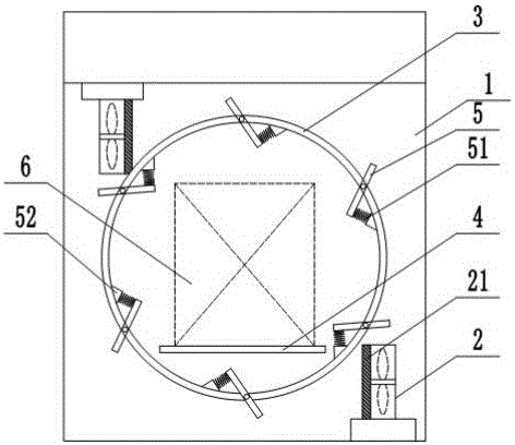
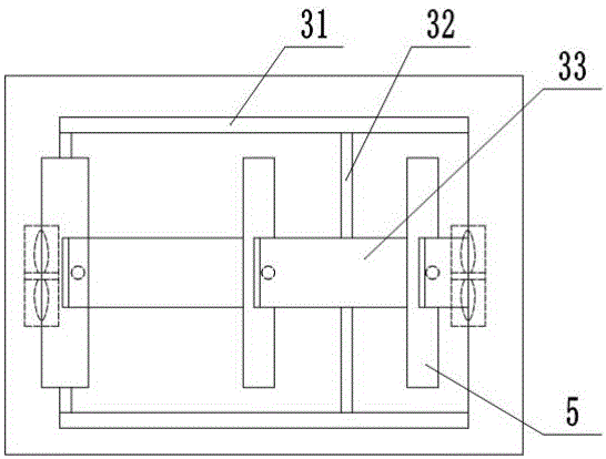
[0016] The reference signs in the drawings of the description include: box body 1, hot air blower 2, protective cover 21, flow guide frame 3, outer frame 31, connecting rod 32, installation ring 33, support plate 4, deflector plate 5, spring 51 , installation block 52, timber 6.

[0017] The embodiment is basically as attached figure 1 and figure 2 Shown:

[0018] A wood drying room with flow guide device, mainly composed of a box body 1, a hot air blower 2 and a support plate 4 for preventing wood 6, and also includes a flow guide frame 3, which is rotatably connected in the box body 1 , the deflector 5 is circular, and the deflector frame 3 includes two circular outer frames 31 and some connecting rods 32 connecting the two outer frames 31 together. Arranged mounting ring 33. Through the arrangement of the outer frame 31, the connecting rod 32 and the installation...


PUM


Abstract

The invention relates to the technical field of solid material drying, and particularly discloses a wood drying chamber with a flow guiding device. The wood drying chamber comprises a box, air heaters, a supporting plate and a flow guiding frame. The flow guiding frame is rotationally connected in the box, flowing guiding plates are circular, the multiple flow guiding plates are rotationally connected to the outer edge of the flow guiding frame, and a spring is connected between the end portion of each flow guiding plate and the flow guiding frame. The two ends of the supporting plate are connected to the inner wall of the box. The supporting plate penetrates the flow guiding frame so that wood on the supporting plate can be located in the middle of the flow guiding frame. The two air heaters are arranged at the upper end and the lower end of the box correspondingly. The facing direction of the air heaters is the outer edge direction of the flow guiding frame, and the wind direction of the two air heaters is the anticlockwise or clockwise rotation direction of the flow guiding frame. Through the rotary flow guiding frame, circulation of high-temperature gas in the box is accelerated, through the arrangement of the flow guiding plates with the changeable angle, distribution of high-temperature airflow around the wood can be more uniform, the situation of serious local heating is avoided, and the wood drying quality is improved.

Description

technical field [0001] The invention relates to the technical field of dry solid materials. Background technique [0002] The door panel must be dried before processing to remove excess water to improve the durability of the door panel. At present, the drying method of wood is mainly to pile up the wood in the wood drying room equipped with forced air circulation fan, heat exchanger, humidity control and detection device according to certain requirements. The air flows through the heat exchanger and the surface of the wood according to certain rules, transfers heat to the wood, and at the same time mixes the moisture evaporated from the wood in the air and discharges it to the outside. Among various types of drying chambers, the aerodynamic performance of the top-fan type drying chamber is superior to that of the end-fan type and the side-fan type, with fewer twists and turns in the structure, less gas movement resistance, and better airflow distribution than the other two ...

Claims


Application Information

Patent Timeline
Patent Type & Authority Applications(China)
IPC IPC(8): F26B9/06F26B21/00
CPCF26B9/06F26B21/004F26B2210/16
Inventor 卢川
Owner CHONGQING KUNXIU DOOR & WINDOW
Learn More