

Weld bead dimension zero-lag real-time detection device for arc additive manufacturing and real-time detection method
A technology of additive manufacturing and real-time detection, applied in measurement devices, optical devices, instruments, etc., can solve the problems of non-lag detection, inability to realize the width and height of the cladding channel, and achieve the effect of non-lag visual sensing
- Summary
- Abstract
- Description
- Claims
- Application Information
AI Technical Summary
Problems solved by technology
Method used
Image

Examples
specific Embodiment approach 1
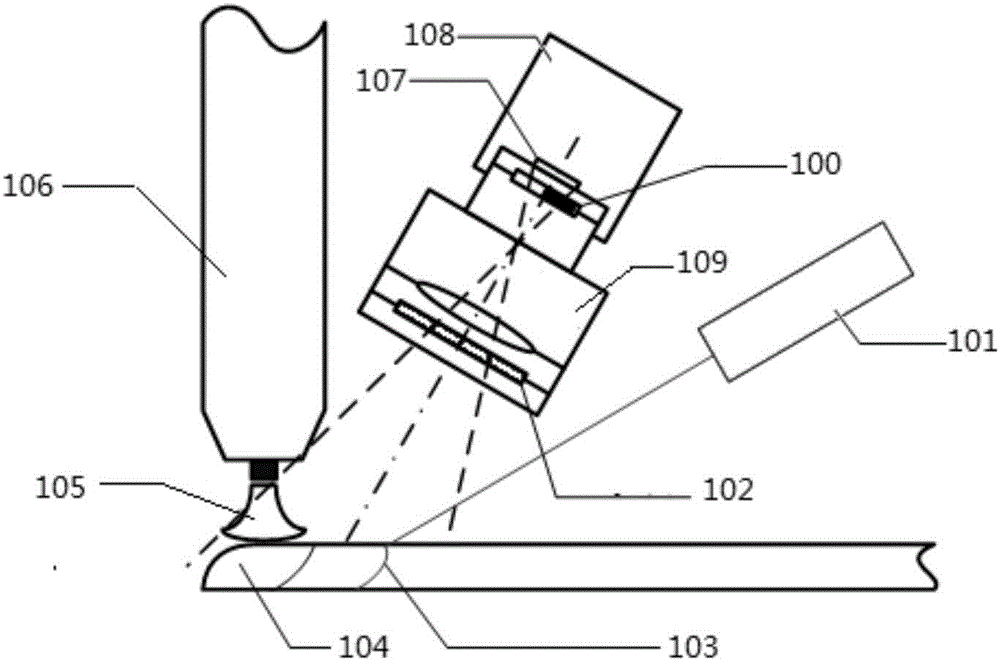
[0016] Specific implementation mode one: the following combination figure 2 This embodiment is described. The device for detecting the size of the welding path in arc additive manufacturing without hysteresis in real time according to this embodiment includes a partition light reduction element 100, a line structured light generator 101, an optical filter 102, and a CCD camera 108. and lens 109;
[0017] Lens 109 is installed on the front end of the imaging target surface 107 of CCD camera 108, and optical filter 102 is installed on the front end of lens 109 interior, and the laser stripe 103 that line structured light generator 101 emits is projected to molten pool 104 rear, and laser stripe 103 and There is a distance between the molten pool 104, the welding torch 106 is vertically arranged directly above the molten pool 104, and the arc 105 produced by the welding torch 106 is located at the upper end of the molten pool 104;
[0018] Between the imaging target surface 107...
specific Embodiment approach 2
[0020] Specific implementation mode two: the following combination figure 2 This embodiment will be described. This embodiment will further describe the first embodiment. The zoned light reduction element 100 is composed of light reduction sheets of different sizes and different light transmittances.
[0021] In this embodiment, different areas of the partition light reduction element 100 have different light transmittances, therefore, the arc 105 generated by the welding torch 106, the molten pool 104, and the laser stripes 103 projected by the line structured light generator 101 on the welding path are all It can be clearly imaged on the imaging target surface 107 of the CCD camera 108 .
specific Embodiment approach 3
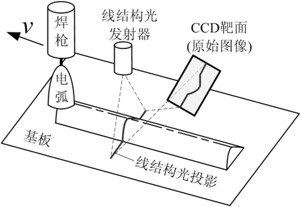
[0022] Specific implementation mode three: the following combination figure 2 This embodiment is described. The real-time detection method used in this embodiment is used for the real-time detection device of arc additive manufacturing welding path size without lag. The real-time detection method can realize a CCD visual image and see the high-temperature deposited metal and laser The stripes 103 realize the lag-free real-time detection of the size of the welding path in arc additive manufacturing. The specific method is: the partition dimming element 100 controls the amount of light entering the molten pool 104 to be lower than that of the laser stripe 103, so that the partition is dimmed and then welded The radiation intensity of the metal spectrum is at the same level as the light intensity of the laser stripes 103 .
[0023] In the present invention, in arc additive manufacturing, the four light sources are sorted in descending order of average brightness, which are: arc ...
PUM
 Abstract
Description
Claims
Application Information