
Casting blank surface temperature field measurement sensor and casting blank surface temperature field measurement method

A technology for measuring sensors and surface temperature, applied in the field of sensors, can solve the problems of narrow measurement range, difficult to measure stably, and difficult to measure the real temperature of the slab surface accurately and stably, and achieve the effect of suppressing random noise and reducing additional errors

Inactive Publication Date: 2017-05-10
LIAONING UNIVERSITY OF PETROLEUM AND CHEMICAL TECHNOLOGY
View PDF5 Cites 6 Cited by
  • Summary
  • Abstract
  • Description
  • Claims
  • Application Information

AI Technical Summary

Problems solved by technology

The key issues are: the uncertainty of the surface emissivity of the slab and the interference factors such as smoke and water mist are difficult to achieve true temperature measurement; the influence of randomly distributed oxide scales on the surface is difficult to achieve stable measurement; the temperature gradient up to 400 °C is difficult to achieve for different species The steel billets are measured with equal precision in each temperature range
The shortcomings of the above two methods are: First, neither the infrared thermal imager nor the infrared thermometer can overcome the uncertain influence of the emissivity of the surface of the slab, and can only be regarded as a black body or artificially set emissivity. Therefore, the measurement results of the above methods are difficult to reflect the real temperature of the surface of the slab; secondly, conventional thermal imaging cameras or thermometers cannot overcome the temperature measurement errors caused by water vapor and smoke; thirdly, although the model filtering can overcome the The temperature measurement fluctuates, but due to the large differences in the components of different steel types, the model established through the production process is difficult to be universal, and the correction of the temperature measurement results based on this is difficult to ensure the measurement accuracy
These estimated values ​​cannot accurately reflect the radiant energy of the measured target, so it is difficult to measure the real temperature of the target; secondly, the dynamic temperature measurement ranges of R, G, and B pixels are very different, and only one wavelength can be used for colorimetric temperature measurement The dynamic range of the wavelength can be fully utilized, while the measurement range of the other two wavelengths is narrow, which cannot meet the needs of measuring the large gradient temperature field of different steel types
[0005] In addition, the calibrated image camera cannot overcome the dark current noise of the CCD online, resulting in the measurement accuracy of the low temperature section being much lower than that of the high temperature section, and it is difficult to achieve equal precision measurement of the entire temperature section
[0006] During the continuous casting process, the slab is in a strong oxidation and strong water cooling environment. Due to the influence of the non-deterministic surface emissivity of the slab, the interference of smoke and water vapor, and the random distribution of scale, the deficiency of the existing technology is mainly the use of conventional radiation temperature measuring instruments. It is difficult to accurately and stably measure the real temperature of the surface of the slab, and secondly, it is difficult to achieve equal precision measurement of the large gradient temperature field of multiple steel types

Method used


Image

  • Casting blank surface temperature field measurement sensor and casting blank surface temperature field measurement method
  • Casting blank surface temperature field measurement sensor and casting blank surface temperature field measurement method
  • Casting blank surface temperature field measurement sensor and casting blank surface temperature field measurement method

Examples


Embodiment Construction

[0035] Exemplary embodiments of the present disclosure will be described in more detail below with reference to the accompanying drawings. Although exemplary embodiments of the present disclosure are shown in the drawings, it should be understood that the present disclosure may be embodied in various forms and should not be limited by the embodiments set forth herein. Rather, these embodiments are provided for more thorough understanding of the present disclosure and to fully convey the scope of the present disclosure to those skilled in the art.

[0036] In order to make the advantages of the technical solution of the present invention clearer, the present invention will be described in detail below in conjunction with the accompanying drawings and embodiments.

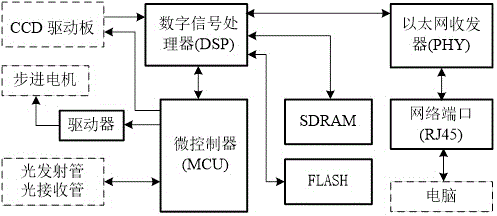
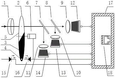
[0037]The embodiment of the present invention provides a sensor for measuring the surface temperature field of the slab, such as figure 1 As shown, the measurement sensor includes: an optical lens 100 , a stepping m...


PUM


Abstract

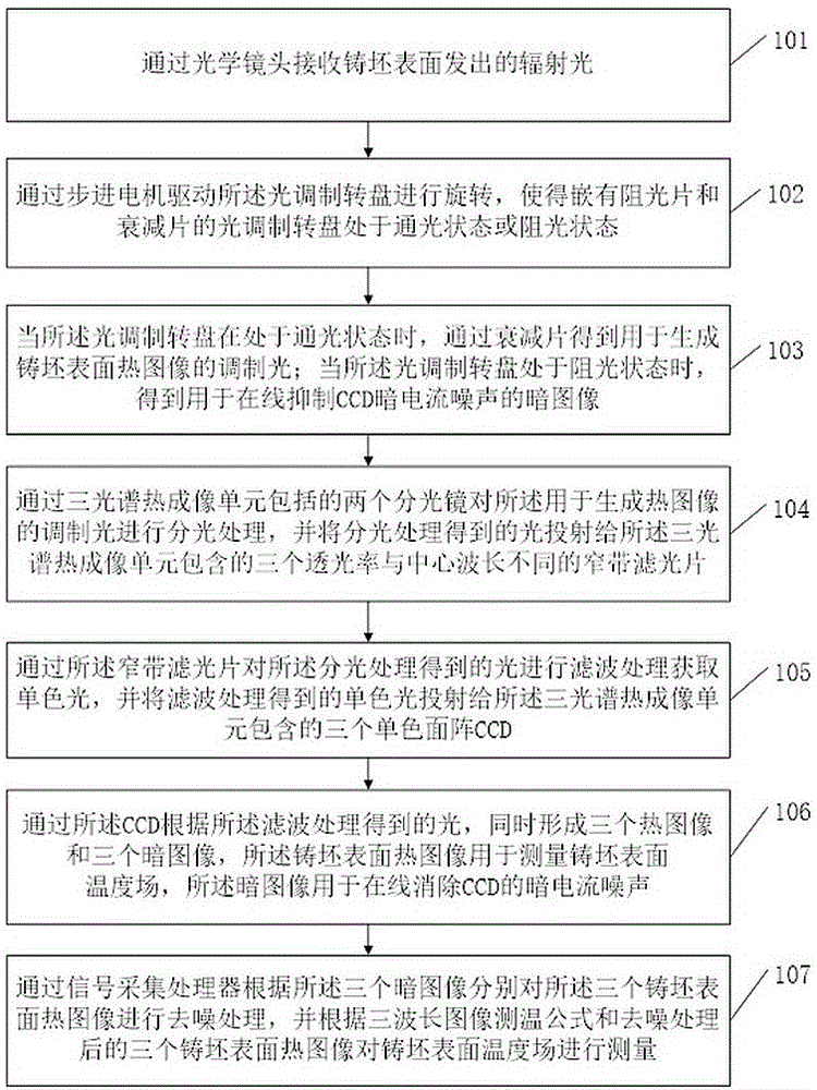
The invention discloses a casting blank surface temperature field measurement sensor and a casting blank surface temperature field measurement method, wherein the casting blank surface temperature field measurement sensor and the casting blank surface temperature field measurement method relate to the technical field of sensors. The sensor and the method mainly aim to overcome a defect of temperature field measurement inaccuracy caused by casting blank surface emissivity uncertainty, smoke, steam and oxidation scale interference, thereby realizing accurate, stable and continuous measurement for the casting blank surface temperature field. The casting blank surface temperature field measurement sensor comprises the components of an optical lens, a stepping motor, an optical modulation turntable on which a light blocking plate and an attenuation plate are embedded, a three-spectrum thermal imaging unit, and a signal acquisition processor. The three-spectrum thermal imaging unit comprises the components of two spectroscopes, two narrowband optical plates with light transmittances which are different from wavelength, and three monochromatic surface arrays CCD.

Description

technical field [0001] The invention relates to the technical field of sensors, in particular to a sensor and method for measuring the surface temperature field of a slab. Background technique [0002] In the continuous casting process, the surface temperature of the slab is of great significance to optimize the secondary cooling system and improve the quality of the slab, and its accurate online measurement is a technical problem that has not yet been solved in the metallurgical industry. The key issues are: the uncertainty of the surface emissivity of the slab and the interference factors such as smoke and water mist are difficult to achieve true temperature measurement; the influence of randomly distributed oxide scales on the surface is difficult to achieve stable measurement; the temperature gradient up to 400 °C is difficult to achieve for different species The steel billets are measured with equal precision at each temperature range. [0003] At present, a number of ...

Claims


Application Information

Patent Timeline
Patent Type & Authority Applications(China)
IPC IPC(8): G01J5/00
CPCG01J5/00
Inventor 白海城
Owner LIAONING UNIVERSITY OF PETROLEUM AND CHEMICAL TECHNOLOGY
Learn More