Fault characteristic extraction method for non-stationary signal of gear box

A non-stationary signal, fault feature technology, applied in the direction of machine gear/transmission mechanism testing, measuring devices, instruments, etc., can solve the problems of gearbox fault feature separation and lack of research results.

Active Publication Date: 2017-05-10
SOUTH CHINA UNIV OF TECH
View PDF5 Cites 16 Cited by
  • Summary
  • Abstract
  • Description
  • Claims
  • Application Information

AI Technical Summary

Problems solved by technology

However, most of the research results are limited to the separation of gearbox fault features under steady-state conditions, and the research results for non-stationary signals are relatively scarce

Method used


Image

  • Fault characteristic extraction method for non-stationary signal of gear box
  • Fault characteristic extraction method for non-stationary signal of gear box
  • Fault characteristic extraction method for non-stationary signal of gear box

Examples


Embodiment 1

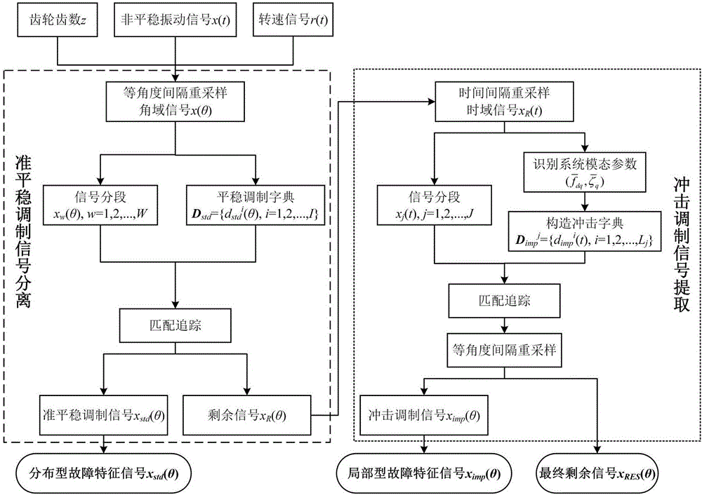
[0090] like figure 1 , this embodiment discloses a method for extracting non-stationary signal fault features of gearboxes based on sparse decomposition and order tracking, which can be used for fault diagnosis of stationary faults and impact faults in gearboxes under variable speed conditions. Specifically include the following steps:

[0091] S1. Synchronously collect the time-domain vibration acceleration signal and speed signal of a measurement point of the gearbox case under variable speed conditions.

[0092] specific:

[0093] S1-1. Establish a space coordinate system XYZ, where the positive direction of the X-axis points to the direction from the input shaft to the output shaft of the central axis of the gearbox, the positive direction of the Z-axis is vertically upward, and the positive direction of the Y-axis is determined by the right-hand rule;

[0094] S1-2. Install a unidirectional acceleration sensor on the surface of the bearing seat of the gearbox, the test ...

Embodiment 2

[0147] This embodiment specifically illustrates the non-stationary fault feature extraction method of a gearbox based on sparse decomposition and order tracking disclosed by the present invention through a fault simulation test of an automobile transmission:

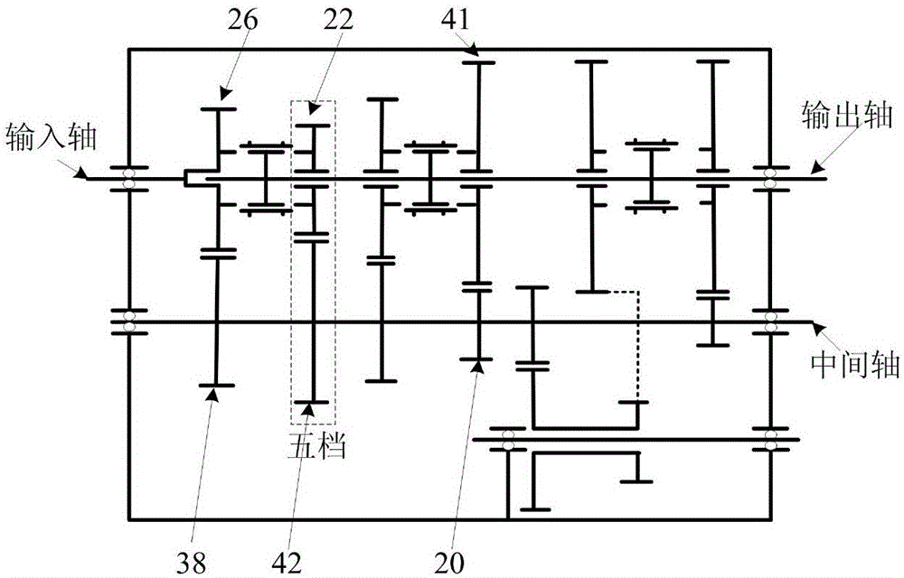
[0148] The tested gearbox is a three-shaft five-speed automotive manual transmission, and its structure is as follows: figure 2 As shown in , the set fault type is broken teeth of the fifth gear output gear. Taking the input shaft as the reference shaft, the number of teeth and characteristic parameters of the gears at each stage are listed in Table 1. The data acquisition system is Muller-BBM.

[0149] Table 1 Experimental test gear box operating parameters

[0150]

[0151] This embodiment is realized through the following specific steps:

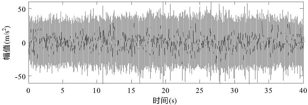
[0152] (1) Synchronously collect the time-domain vibration acceleration signal and speed signal of a measuring point on the gear box under the variable speed condition. The s...


PUM


Abstract

The invention discloses a fault characteristic extraction method for a non-stationary signal of a gear box. The method comprises the following steps: synchronously gathering a time domain vibration acceleration signal and a rotating speed signal of the gear box in a variable speed working condition; performing order tracking on the vibration acceleration signal to acquire an angular domain vibration acceleration signal; constructing a stationary modulation dictionary and segmenting the signal in complete alternation; performing a matching pursuit algorithm on the signal in each section, and reconstructing a quasi-stationary modulation signal in the signal; converting the residual angular domain signal into a time domain signal; recognizing a multiple-order inhered frequency and a damping ratio of the gear box from the residual signals; segmenting the residual time domain signal to construct an impact modulation dictionary; extracting an impact modulation component in the signal by virtue of the matching pursuit algorithm, and performing order tracking on the impact modulation component; and analyzing the order domain characteristic of the extracted signal for fault diagnosis. By applying a sparse decomposition method to characteristic extraction for the non-stationary signal of the gear box in the variable working condition, the calculating speed and the matching precision of the signal can be improved.

Description

technical field [0001] The invention relates to the field of rotating machinery and signal processing, in particular to a method for extracting a fault feature of a gearbox non-stationary signal. Background technique [0002] Since the vibration signal contains a wealth of dynamic information of the gearbox, the analysis of the vibration signal has always been the most important means for the monitoring and fault diagnosis of the gearbox. [0003] In actual engineering, due to the influence of factors such as load changes and speed up and down, the gearbox is often in a variable speed working state, and its vibration response signal is a non-stationary signal, and the characteristic frequency component of the signal is time-varying related to the speed. Traditional analysis methods are no longer applicable, so researchers proposed time-frequency analysis methods (such as short-time Fourier transform, Wigner distribution, Hilbert-Huang transform) and time-scale analysis metho...

Claims


Application Information

Patent Timeline
Patent Type & Authority Applications(China)
IPC IPC(8): G01M13/02
CPCG01M13/021G01M13/028
Inventor 李永焯丁康何国林林慧斌杨小青吴兆乾
Owner SOUTH CHINA UNIV OF TECH
Why Eureka
Try Eureka