
Loadable permeability test device

A permeation device and permeameter technology, applied in the field of geotechnical engineering, can solve problems such as soil compression deformation, soil permeability change, pore change, etc.

Pending Publication Date: 2017-05-10
WUHAN UNIV OF SCI & TECH
View PDF5 Cites 10 Cited by
  • Summary
  • Abstract
  • Description
  • Claims
  • Application Information

AI Technical Summary

Problems solved by technology

[0003] The permeability meter is often used to measure the permeability coefficient of the soil. It belongs to a conventional geotechnical instrument. The permeability coefficient of the soil is closely related to the type of the soil itself, the structure of the soil, the temperature, the state of the load, etc., which is very complicated.
However, the function of the existing geotechnical instrument permeameter is relatively single. The existing permeation device can only measure the static permeability characteristic parameters of the soil under the natural stress condition, and cannot simulate the permeability coefficient of the soil under the action of external load according to the actual situation. This is inconsistent with the actual soil environment. The actual soil is often subjected to loads, environmental loads, and construction loading and unloading, which will lead to changes in the permeability characteristics of the soil itself. The measurement of the permeability coefficient is also very important. For example, in a construction project, as the building is built, the load on the upper part of the lower soil is also in a process of change. For example, the excavation and landfill of the surrounding soil will lead to the loading and unloading of the soil, plus the entry and exit of personnel, equipment vibration and The construction load will make the soil often be in the environment of static load and dynamic load. Such external loads will cause the soil to compress and deform, the pores of the soil will be compacted, and its permeability coefficient will also change.
For another example, for sandy soil, its particle size does not move, and it is often regarded as sand particles with continuous particle size in soil theory. Fine particles and large particles together form the skeleton of the soil. In some hydrodynamic forces In places with rich environments, such as seaside embankments or beaches, due to frequent water level fluctuations, such as tides, under the action of hydrodynamic forces, the fine particles of the sandy soil skeleton will flow under the action of water flow. Its position changes accordingly, and the permeability coefficient of the soil will also change accordingly; it can only measure the change of the permeability of the soil under the condition of no loading, which cannot match the actual engineering background; at the same time, in some alternating wet and dry In frequent areas, there will also be repeated rainfall and evaporation cycles in the soil. The flow of gas in the soil will cause changes in the internal pores of the soil and also lead to changes in the soil permeability coefficient.
Therefore, the existing permeability test cannot measure the actual state of the soil, such as 1. The change of the permeability coefficient when the vertical load is applied
2. It is impossible to measure the change of soil permeability caused by the fluctuation of water level in the water-facing environment, which leads to the flow of soil, especially the fine particles of sand and soil, which leads to changes in the soil structure.
3. It is impossible to measure the change of the permeability coefficient of the soil under the dry-wet cycle state
4. It is even more impossible to measure the deformation of the soil itself under the action of external loads
Therefore, the existing technology cannot simulate the change of the soil permeability coefficient under the external load according to the actual situation.

Method used


Image

  • Loadable permeability test device
  • Loadable permeability test device
  • Loadable permeability test device

Examples


specific Embodiment approach

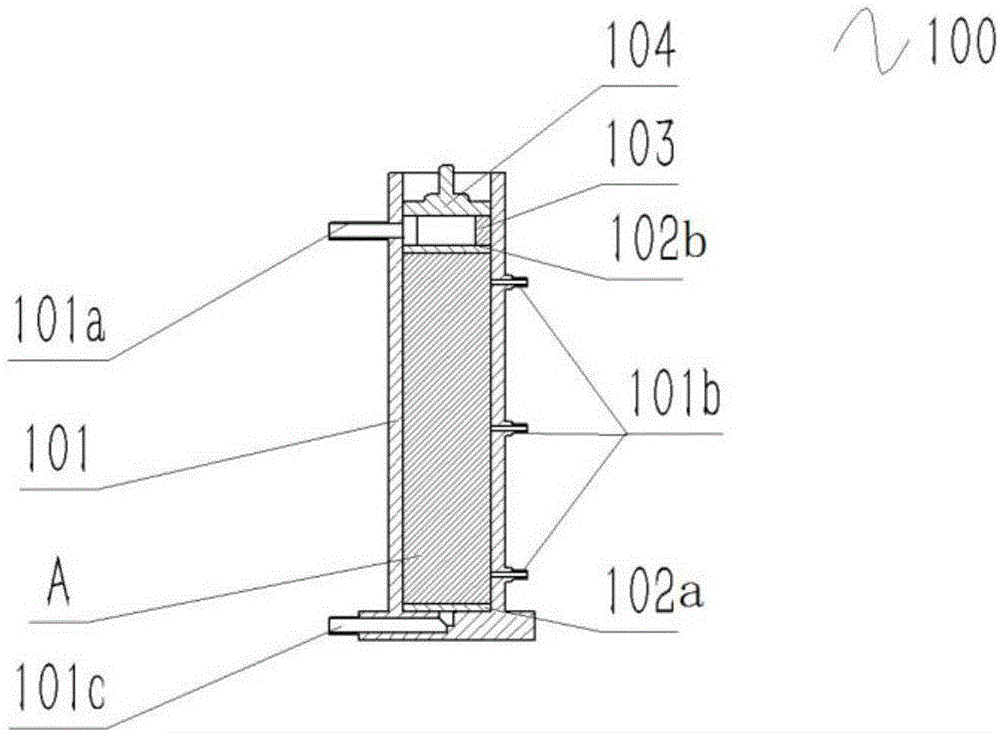
[0051] The specific implementation is as follows: the air pressure system 210 provides a power source, which is applied to the permeable stone 102 and the sample through the loading cover 104 and the ring with holes 103 in sequence. The pneumatic circuit control system controls the loading method, application size and application time. Impact load, constant static pressure load and cyclic static pressure load can be applied to the sample through three air circuit connection methods: impact load connection mode, constant pressure static pressure load connection mode and cyclic static pressure load connection mode.

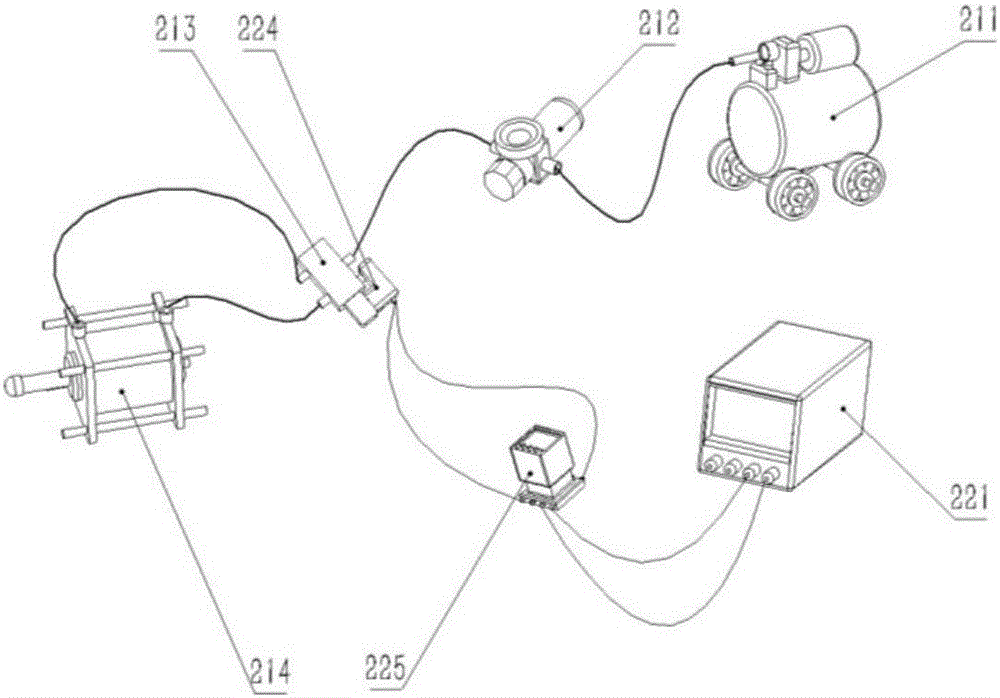
[0052] Wherein, when the load of the vertical load loading module 200 is an impact dynamic load, such as image 3 The specific structure shown is: including a DC power supply 221 connected in sequence, a time relay 225 and a solenoid valve 224 connected in sequence in a circuit; 214 , the solenoid valve 224 is installed on the cylinder switch 213 for controlling th...


PUM


Abstract

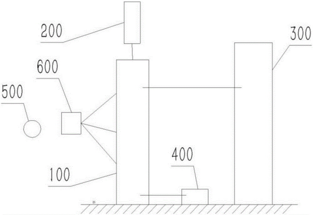
The invention discloses a loadable permeability test device. The loadable permeability test device comprises a permeability instrument, a sensor acquiring module, a vertical load loading module, a water level fluctuation module, a dry and wet circulating module and a sample deformation monitoring module, wherein the sensor acquiring module is used for acquiring permeability parameters of a sample; the vertical load loading module is arranged on the top of the permeability instrument and is used for providing vertical load for the sample; the water level fluctuation module is connected to one side of the permeability instrument and is used for simulating tide load; the dry and wet circulating module is connected to the bottom of the permeability instrument and is used for simulating rainfall and evaporation; and the sample deformation monitoring module is arranged on a side of the permeability instrument, and is used for observing and recording deformation of the sample in an experimentation process.

Description

technical field [0001] The invention relates to the field of geotechnical engineering, in particular to a loadable penetration test device. [0002] technical background [0003] The permeability meter is often used to measure the permeability coefficient of soil, which belongs to a conventional geotechnical instrument. The permeability coefficient of soil is closely related to the type of soil itself, soil structure, temperature, and the state of the load, which is very complicated. However, the function of the existing geotechnical instrument permeameter is relatively single. The existing permeation device can only measure the static permeability characteristic parameters of the soil under the natural stress condition, and cannot simulate the permeability coefficient of the soil under the action of external load according to the actual situation. This is inconsistent with the actual soil environment. The actual soil is often subjected to loads, environmental loads, and cons...

Claims


Application Information

Patent Timeline
IPC IPC(8): G01N15/08G01B11/16
CPCG01B11/16G01N15/0806G01N15/0826
Inventor 王帅雷学文董云洁孟庆山张中信徐亚飞李雨杰周疆豪廖明勇谢凌峰陈斌许九保罗恒
Owner WUHAN UNIV OF SCI & TECH
Learn More