Wireless timing method for recording type fault indicator

A fault indicator, wireless technology, applied in radio-controlled timers, instruments, measuring devices, etc., can solve problems such as fault indicator clock deviation, and achieve the effects of controllable time accuracy, cost reduction, and improved energy management efficiency

Active Publication Date: 2017-05-10
FUJIAN AUTOMATION ELECTRIC POWER TECH
View PDF5 Cites 9 Cited by
  • Summary
  • Abstract
  • Description
  • Claims
  • Application Information

AI Technical Summary

Problems solved by technology

[0004] The present invention is achieved in the following way: a wireless timekeeping method for a wave-recording fault indicator, the method is used to solve the high-precision, low-power consumption time-setting and punctuali

Method used


Image

  • Wireless timing method for recording type fault indicator
  • Wireless timing method for recording type fault indicator
  • Wireless timing method for recording type fault indicator

Examples


Embodiment Construction

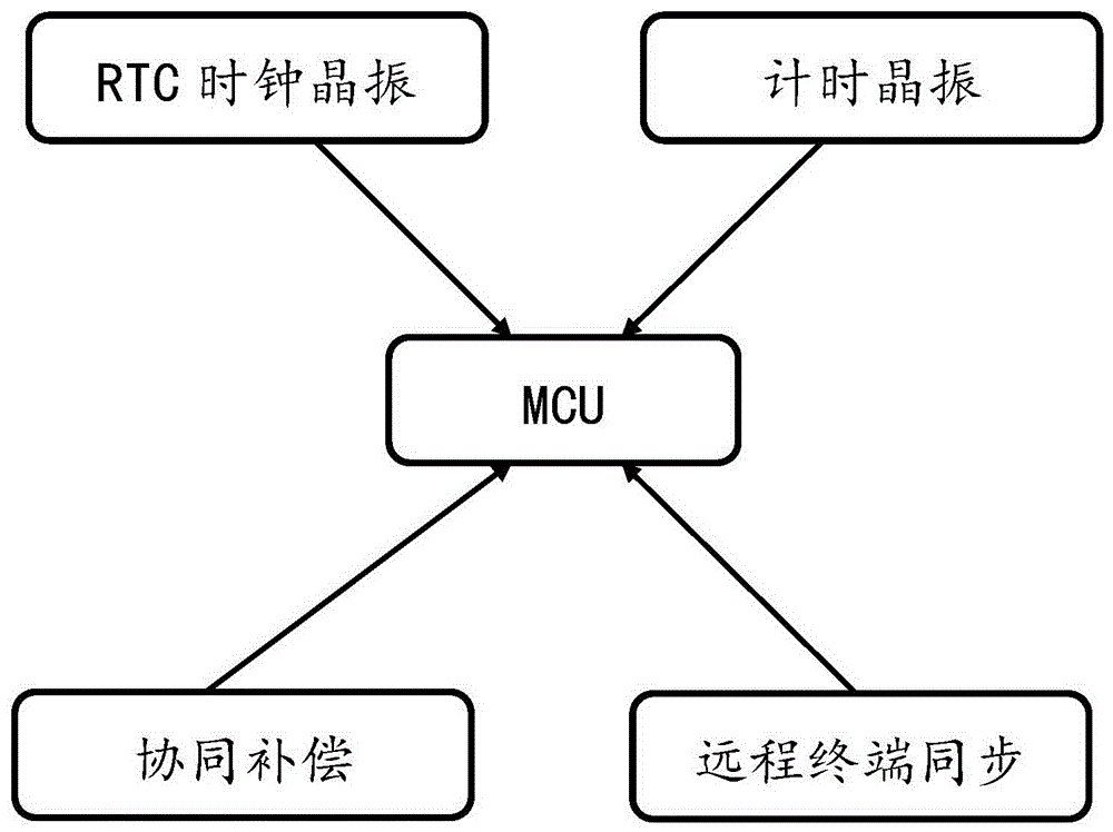
[0022] see figure 1 and figure 2 As shown, a wireless timekeeping method for a wave-recording type fault indicator of the present invention is used to solve the high-precision time-setting and time-keeping requirements of a fault indicator with a wave-recording function.

[0023] (1) The method of using multi-crystal oscillators to work together.

[0024] (2) The time calibration step is 1 μs, and the clock deviation of the three-phase fault indicator can reach within 25 μs.

[0025] (3) This method has the characteristics of ultra-low power consumption and low cost.

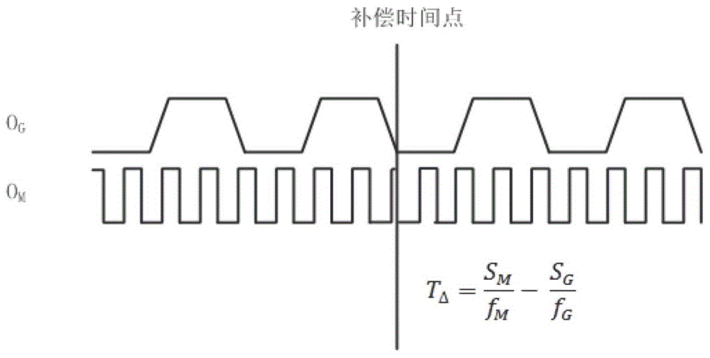
[0026] Using multi-crystal oscillators to work together, at least one medium-precision high-frequency timing crystal oscillator and one high-precision low-frequency RTC clock crystal oscillator should be configured. The high-frequency medium-precision crystal oscillator is calibrated by the low-frequency high-precision crystal oscillator, and the high-frequency crystal oscillator provides compensation data t...


PUM


Abstract

The invention provides a wireless timing method for a recording type fault indicator. The method is used for satisfying a requirement of low-power-consumption timing requirement in the fault indicator with a recording function. A multi-crystal-oscillator cooperation manner is utilized in the method. A time calibration step is 1 [mu]s, and the clock error of the fault indicator is within 25 [mu]s. The timing method mainly satisfies requirements for high synchronization precision and low time synchronism loss in a novel fault indicator with the recording function. Multi-crystal-oscillator cooperation technology is utilized. Full-time-period time precision can be sustained to 5ppm. A high-real-time-performance timing mode is combined. Compared with traditional wireless timing technology, the timing method of the invention has an advantage that the compensation step can reach 1 [mu]s. Through the manner of the invention, the clock error of the thee-phase fault indicator can be lowered to a range within 30 [mu]s. Furthermore the three-phase fault indicator has an advantage of ultralow power consumption.

Description

technical field [0001] The invention relates to the technical field of fault indicators, in particular to a wireless timekeeping method for a wave-recording type fault indicator. Background technique [0002] The fault indicator with wave recording function needs to monitor the line current and electric field state in real time in the running line, and record the line waveform in time when the measured quantity is disturbed, so as to provide a basis for fault analysis. During the operation of the traditional fault indicator, due to the small difference in the manufacturing of the crystal oscillator and the problem of timing technology, it will cause the problem of out-of-synchronization during the operation. The wave recording function has high requirements on the synchronization of the three-phase fault indicators. At a sampling rate of 4KHz, the synchronization accuracy of the three-phase fault indicators needs to be within 100μs. Contents of the invention [0003] The ...

Claims


Application Information

Patent Timeline
IPC IPC(8): G04R20/00G01R31/00
CPCG01R31/00G04R20/00
Inventor 吴孝彬黄景辉郭磊王军锋余招军庄小龙江伟梁丽军孙振业黄星敏梁安韬
Owner FUJIAN AUTOMATION ELECTRIC POWER TECH
Why Eureka
Try Eureka