
Anti-condensation ring main unit and ant-condensation method

A ring network cabinet and anti-condensation technology, applied in the direction of non-electric variable control, instrumentation, humidity control, etc., can solve problems such as safety accidents, no way to avoid condensation, and low power of the dehumidifier

Active Publication Date: 2017-05-10
ZHEJIANG DUMEI ELECTRIC POWER TECH
View PDF6 Cites 7 Cited by
  • Summary
  • Abstract
  • Description
  • Claims
  • Application Information

AI Technical Summary

Problems solved by technology

Due to the limited power of the ring network cabinet, the power of the dehumidifier is small. When a large amount of water vapor enters the cabinet, the dehumidification effect is very insignificant.
[0005] Condensation phenomenon is caused by the joint action of temperature and humidity. When the temperature and humidity in the air are unevenly distributed, condensation is very easy to occur in areas and interfaces with large differences between cold and heat and humidity. Using traditional dehumidification methods, although When the humidity in the cabinet is not high, reduce the humidity appropriately. However, there is no way to eliminate the uneven distribution of humidity and temperature in the cabinet, and there is no way to avoid condensation.
[0006] The condensation phenomenon on the electrical components on the electrical insulation will cause creepage and flashover accidents, which will aggravate the insulation performance of the equipment, seriously affect the service life of the equipment, and cause safety accidents when the discharge is serious

Method used


Image

  • Anti-condensation ring main unit and ant-condensation method
  • Anti-condensation ring main unit and ant-condensation method
  • Anti-condensation ring main unit and ant-condensation method

Examples


Embodiment Construction

[0031] The present invention will be described in further detail below in conjunction with the accompanying drawings.

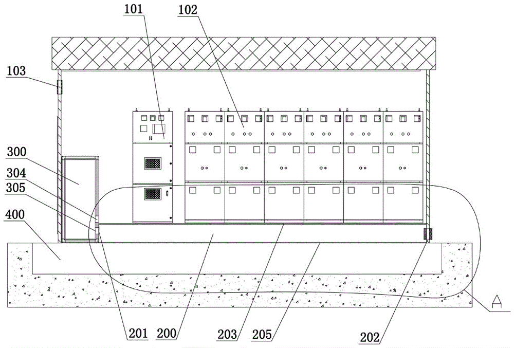
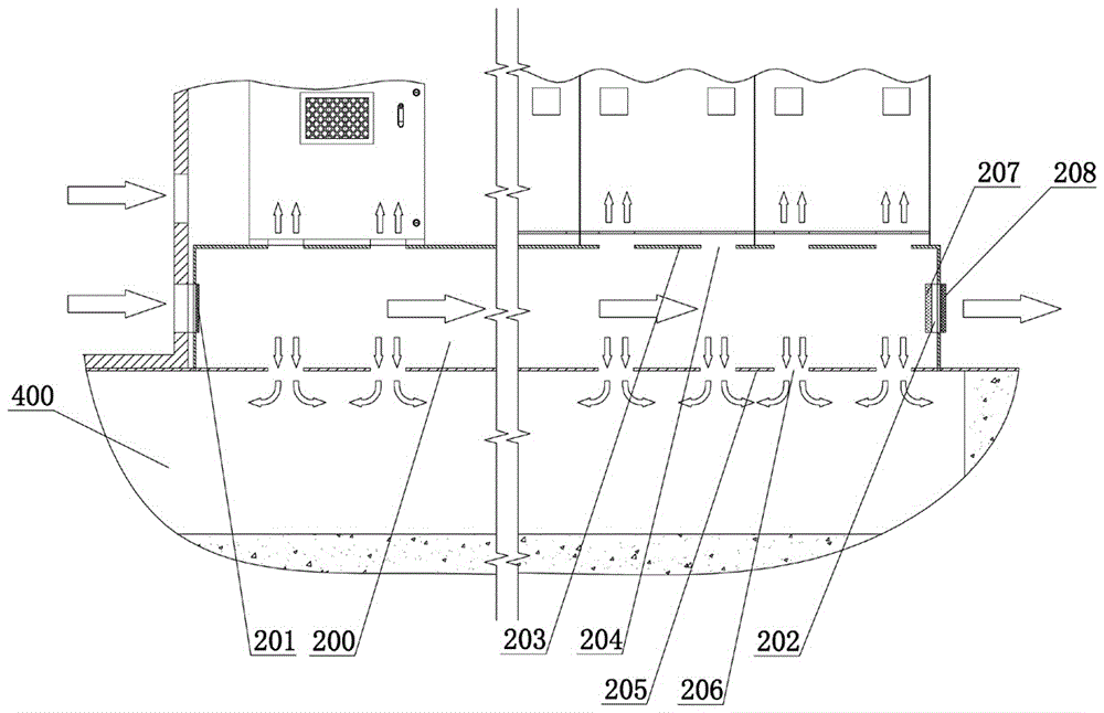
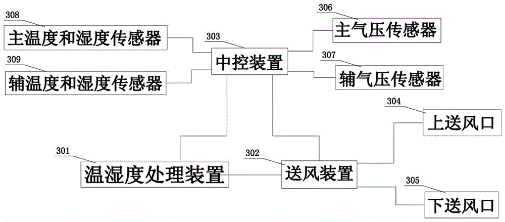
[0032] An anti-condensation ring network cabinet, including an intelligent isolation and moisture-proof processing chamber 200; the intelligent isolation and moisture-proof processing chamber 200 is installed at the bottom of the ring network cabinet and is located above the cable trench 400; the cable trench 400 is laid with cables and After passing through the intelligent isolation and moisture-proof processing chamber 200, enter the ring network cabinet; one side of the intelligent isolation and moisture-proof processing chamber 200 is provided with an air inlet 201, and the other side is provided with a pressure relief window 202; the air inlet 201 is connected to the environment regulating device 300, and A pressure relief valve 207 is installed in the pressure window 202 ; an environment regulating device 300 is installed inside the ring network cabinet,...


PUM

PropertyMeasurementUnit
Diameteraaaaaaaaaa

Abstract

The invention discloses an anti-condensation ring main unit, and belongs to the technical field of ventilation of a ring main unit; the anti-condensation ring main unit comprises an intelligent isolating and moisture-proof processing cavity; the intelligent isolating and moisture-proof processing cavity is installed at the bottom part of the ring main unit and located above a cable ditch; the cable ditch is paved with a cable, and the cable enters the ring main unit after crossing through the intelligent isolating and moisture-proof processing cavity; one side of the intelligent isolating and moisture-proof processing cavity is provided with an air inlet, and the other side is provided with a pressure relief window; the air inlet is connected with an environment adjusting device, and the pressure relief window is equipped with a pressure relief valve; the environment adjusting device is installed at the inner part of the ring main unit, and comprises a temperature humidity processing device and an air delivery device. Through arranging the intelligent isolating and moisture-proof processing cavity, the device can prevent vapor evaporated by the cable ditch from entering the cabinet body, and thereby fundamentally reducing wet gas at the inner part of the cabinet body, decreasing the work load of the environment adjusting device, effectively reducing air humidity in the ring main unit and stopping condensation.

Description

technical field [0001] The invention belongs to the technical field of ring network cabinet ventilation, and in particular relates to a condensation-proof ring network cabinet and a condensation-proof method. Background technique [0002] With the rapid development of the national economy and power grid construction, the ring network cabinet, that is, the ring network power supply unit RMU, as a kind of convenient installation and use, small footprint, not limited by location, etc., is a new emerging in recent years. , The fast-growing smart grid power distribution equipment is mainly used in power distribution equipment such as radioactive, main line and ring network power supply switching stations, terminal distribution stations, and outdoor box-type distribution stations. [0003] The ring network cabinet is generally installed outdoors. There is a cable trench in the lower part of the cabinet. Some cables are coiled in the cable trench. Enter the ring network cabinet wi...

Claims


Application Information

Patent Timeline
IPC IPC(8): G05D22/02
CPCG05D22/02
Inventor 张晓勇徐元明胡敏
Owner ZHEJIANG DUMEI ELECTRIC POWER TECH
Learn More