Voltage tracking/embedded circuit

A voltage tracking and clamping technology, applied in the direction of adjusting electrical variables, control/regulation systems, instruments, etc., can solve the problems of output waveform deterioration, inability to overcome the influence of phase compensation capacitor speed, slow response, etc., to improve common mode rejection Ratio, improve zero drift suppression ability, fast response effect

Active Publication Date: 2017-05-10
THE 41ST INST OF CHINA ELECTRONICS TECH GRP
View PDF8 Cites 2 Cited by
  • Summary
  • Abstract
  • Description
  • Claims
  • Application Information

AI Technical Summary

Problems solved by technology

Operational amplifier saturation circuit method When the negative voltage is input, the output of the operational amplifier is saturated internally, and the influence from saturation to reverse recovery time makes the response very slow; from the saturation level to the positive output voltage is limited by the slew rate so that the response Slower; the influence of reverse recovery characteristics also deteriorates the output waveform, so this circuit can only be used for DC or low frequency
The operational amplifier unsaturated circuit method adds a buffer amplifier and negative feedback control on the basis of the operational amplifier saturated circuit method. It is necessary to increase the corresponding phase compensation capacitor to make the circuit work stably. Therefore, although the operational amplifier saturated circuit method overcomes the However, due to the limitation of the conversion rate of the operational amplifier, it is necessary to select a high-speed operational amplifier according to the necessary frequency, which still cannot overcome the speed influence caused by factors such as phase compensation capacitors.
[0003] Due to the growing needs of rapid automatic testing and high-frequency program-controlled testing, the existing voltage tracking / clamping circuit has been unable to meet the needs, so a reliable and effective voltage tracking / clamping circuit and its implementation method are needed to solve the above problems

Method used


Image

  • Voltage tracking/embedded circuit
  • Voltage tracking/embedded circuit
  • Voltage tracking/embedded circuit

Examples


Embodiment Construction

[0019] The specific embodiment of the present invention will be further described below in conjunction with accompanying drawing and specific embodiment:

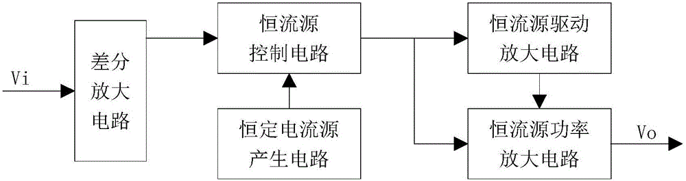
[0020] like figure 1 As described above, a voltage tracking / clamping circuit includes a differential amplifier circuit, a constant current source generating circuit, a constant current source control circuit, a constant current source drive amplifier circuit, and a constant current source power amplifier circuit. The differential amplifier circuit is located at the input end as The preamplifier converts the voltage error signal into a current signal, and the converted current signal flows into the constant current source control circuit, and the current signal flowing into the constant current source control circuit performs a current proportional control operation with the constant current generated by the constant current source generating circuit, The constant current source signal is obtained after the current proportio...


PUM


Abstract

This invention discloses a voltage tracking or an embedded circuit, which specifically relates to semiconductor testing field. The voltage tracking or the embedded circuit comprises the differential amplifier circuit, the constant current source circuit, the constant current source control circuit, the constant current source driving circuit and the constant-current power amplifier circuit. The differential amplifier circuit at the input terminal as a pre-amplifier converts the voltage error signal to current signal. The current signal from the constant current source control circuit and constant current from the constant current source generates the circuit execute current proportioning controlling operation to generate constant current source signal. The constant current source signal flows into the constant current source driving amplifier circuit and constant current source power amplifier circuit respectively.

Description

technical field [0001] The invention belongs to the field of semiconductor testing, and in particular relates to a voltage tracking / clamping circuit. Background technique [0002] In the fields of semiconductor analyzer testing, program-controlled power supply testing, etc., it is often necessary to output positive or negative voltage / current, which requires controlling the junction power tube to output both forward and reverse, especially for When testing the characteristic parameters of high-frequency transistors, it is especially necessary to provide a sequence of high-frequency voltage signals with variable voltage polarity and stable and reliable polarity switching for test analysis. All of these require a voltage tracking / clamping circuit to drive and control the output junction power tube. The existing voltage tracking / clamping circuit generally adopts the operation amplifier saturation circuit method and the operation amplifier unsaturation circuit method. Operatio...

Claims


Application Information

Patent Timeline
Patent Type & Authority Applications(China)
IPC IPC(8): G05F3/26G01R31/26
CPCG01R31/2608G05F3/26
Inventor 王文廷李斌张济民张永坡
Owner THE 41ST INST OF CHINA ELECTRONICS TECH GRP
Why Eureka
Try Eureka