Winding equipment

A technology of winding equipment and equipment racks, which is applied in the direction of electrical components, inductance/transformer/magnet manufacturing, circuits, etc., can solve problems such as the flatness of easily damaged hollow coils, reduce coil production efficiency, and unimproved technical problems, and achieve shortening The length of the waste wire, the design and practicality, and the effect of improving the degree of mechanical automation

Active Publication Date: 2017-05-10
TANAC AUTOMATION
View PDF7 Cites 4 Cited by
  • Summary
  • Abstract
  • Description
  • Claims
  • Application Information

AI Technical Summary

Problems solved by technology

[0003] Obviously, the existing production method can meet the production requirements to a certain extent, but the above-mentioned production method still has at least the following technical defects: ①. After the coil is removed, it needs to be cut twice, which virtually reduces the Coil Production Efficiency
②. The wire groove is set on the jig, and the overall structure is relatively complicated; ③. The length of the cut waste wire is long, and there is unnecessary waste
[0007] First, although the above-mentioned scheme adopts machinery to cut the thread end, which virtually improves the production efficiency, the above-mentioned scheme still does not improve the above-mentioned technical problems;
[0008] Second, the structure of the mechanism is complex and difficult to assemble and manufacture;
[0009] Third, it uses the suction force of the sucker plate mold to drop the hollow coil. The stripping process is cumbersome and inefficient. Secondly, it is easy to damage the flatness of the hollow coil, and the practicability is poor.

Method used


Image

  • Winding equipment
  • Winding equipment
  • Winding equipment

Examples


Embodiment 1

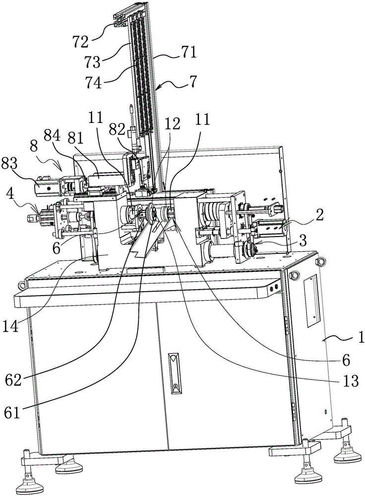
[0038] like figure 1 As shown, the winding equipment includes an equipment rack 1, the equipment rack 1 is a cabinet structure and a U-shaped base 14 is provided on the equipment rack 1, and a wire inlet mechanism located behind the U-shaped base 14 is also provided on the equipment rack 1 7.

[0039] The wire inlet mechanism 7 comprises a vertically arranged bracket 71, and a horizontal bar 72 is provided at the upper end of the bracket, and several pieces of vertically arranged and spaced wire inlet boards 73 are arranged on the horizontal rod 72, and on each wire inlet board 73 A number of discretely arranged wire feed wheels 74 are provided respectively, and the wires to be wound pass through the wire feed wheels 74 on each wire feed board 73 in turn. Of course, they may not pass through all of them. The wire feed can be carried out according to the actual wire feed requirements. the wiring.

[0040] Secondly, the U-shaped base 14 is also provided with a cable-dischargin...

Embodiment 2

[0065] The structure and principle of this embodiment are basically the same as that of Embodiment 1, so it will not be repeated here. The difference is that any one of the jig molds 12 is provided with a hollow space between the two jig molds 12. The coil a breaks away from the stripping mechanism 6 on the molding surface of the jig mold 12 .


PUM


Abstract

The invention relates to winding equipment. Two cylindrical jig shafts are arranged correspondingly on an equipment frame, one cylindrical jig shaft is connected with a first translation driving mechanism, the two cylindrical jig shafts are the same in rotating direction, and the opposite inner ends of the two cylindrical jig shafts are each provided with a jig mold; a jig mandrel is arranged in the other cylindrical jig shaft, wherein the front end of the jig mandrel is sleeved with the corresponding jig mold at the inner end of the cylindrical jig shaft, the jig mandrel is connected with a second translation driving mechanism, the front end of the jig mandrel can stretch outside the forming face of the jig mold arranged at the front end of the jig mandrel in a sleeving mode and make contact with the forming face of the other jig mold, a line pressing and cutting mechanism is arranged between the front end of the jig mandrel and the other jig mold, and a stripping mechanism is arranged on the two jig molds or any jig mold and can make a hollow coil between the two jig molds break away from the forming faces of the two jig molds or the forming face of any one jig mold.

Description

technical field [0001] The invention belongs to the technical field of winding machines, in particular to a winding device suitable for winding hollow coils. Background technique [0002] The coil winding machine is used to wind the wire, and the coils include air-core coils and ordinary coils and so on. Especially for the winding of the hollow coil, when the wire is inserted between the first jig mold and the second jig mold that cooperate with each other in the coil winding machine, the wire end of the wire is penetrated from the slot on the end surface of any jig mold, Then carry out the winding operation, and after the winding is completed, the coil is taken off and then the thread end of the excess length of the wire is cut off. [0003] Obviously, the existing production method can meet the production requirements to a certain extent, but the above-mentioned production method still has at least the following technical defects: ①. After the coil is removed, it needs to...

Claims


Application Information

Patent Timeline
Patent Type & Authority Applications(China)
IPC IPC(8): H01F41/066H01F41/098H01F41/082B21F11/00
CPCB21F11/00
Inventor 钱承林陈八一李艳杰吴翔
Owner TANAC AUTOMATION
Why Eureka
Try Eureka