Eureka AIR delivers breakthrough ideas for toughest innovation challenges, trusted by R&D personnel around the world.

Pressure-proof heat preservation battery compartment

A battery compartment and pressure-resistant technology, which is applied in the direction of secondary batteries, battery pack components, circuits, etc., can solve problems such as equipment failure, harsh environment, and impact on battery performance, so as to avoid storage and discharge capabilities and meet voltage-resistant requirements Effect

Inactive Publication Date: 2017-05-10
熊学军
View PDF9 Cites 5 Cited by
  • Summary
  • Abstract
  • Description
  • Claims
  • Application Information

AI Technical Summary

Problems solved by technology

[0003] As we all know, the bottom of the ocean is not only under huge pressure and low temperature, but also has a very harsh environment. Ordinary batteries cannot withstand such harsh conditions. Once the battery cannot work stably and provide power continuously, all equipment will be unable to operate. For the battery To be able to work safely and stably, the battery must be packaged
[0004] However, the existing battery compartments do not have the function of heat preservation. If the temperature drops, the reaction rate of the electrodes will also drop.
Assuming that the battery voltage remains constant and the discharge current decreases, the power output of the battery will also decrease. It can be seen that the low temperature environment will seriously affect the performance of the battery. Therefore, a pressure-resistant and thermal insulation battery compartment is specially invented.

Method used


Image

  • Pressure-proof heat preservation battery compartment
  • Pressure-proof heat preservation battery compartment

Examples


Embodiment Construction

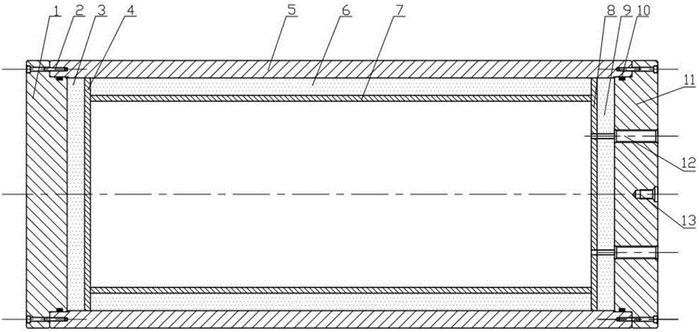
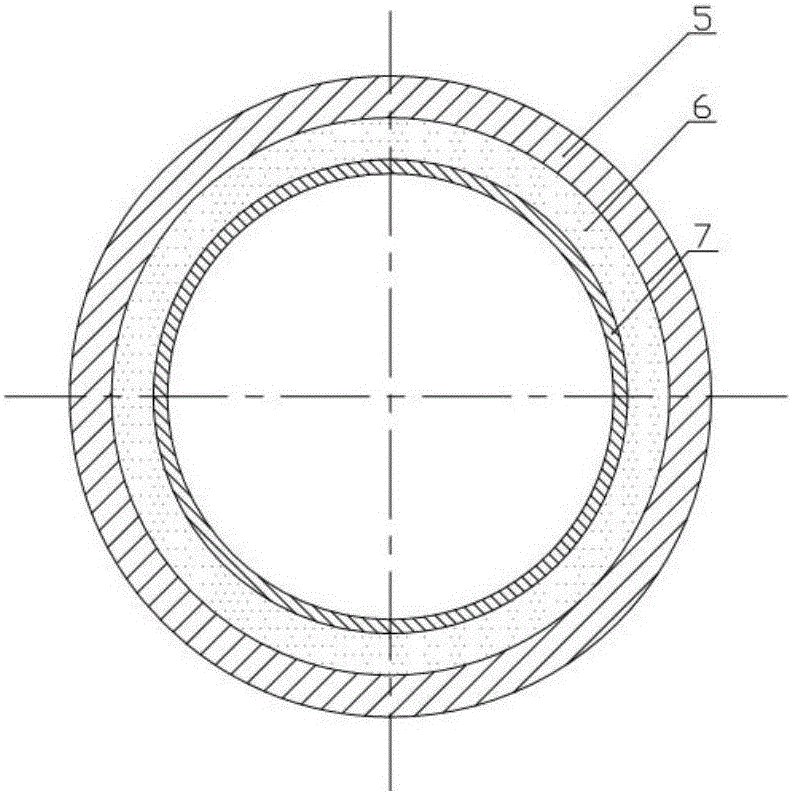
[0013] 1. Structural connection method. The lower flat cover head 1 and the stainless steel cylinder 5 are connected by screws 2, the lower flat cover head 1 and the stainless steel cylinder 5 are sealed by an O-ring 10, and the lower flat cover head 1 and the lower flat cover are combined with a polyurethane foam insulation layer 3 bonded together, the lower flat cover composite polyurethane foam insulation layer 3 and the lower flat cover high-density polyethylene protective layer 4 are bonded together, the stainless steel cylinder 5 and the cylinder composite polyurethane foam insulation layer 6 are bonded together, the cylinder The composite polyurethane foam insulation layer 6 of the body is bonded together with the high-density polyethylene protective layer 7 of the cylinder, and the high-density polyethylene protective layer 8 of the upper flat cover is bonded together with the composite polyurethane foam insulation layer 9 of the upper flat cover. The composite polyure...


PUM


Abstract

The invention belongs to the field of ocean pressure-proof containers, and provides a pressure-proof heat preservation battery compartment. The battery compartment is cylindrical, and comprises an outer 316L stainless steel pressure-roof layer and an inner composite polyurethane heat preservation layer, wherein the outer layer consists of a 316L stainless steel barrel body and 316L stainless steel flat heads arranged at two ends of the barrel body; the stainless steel barrel body is connected with the flat heads at the two ends by adopting screws; the barrel body and the flat heads are sealed by adopting O-shaped rings; a lifting ring connection opening and two watertight plug-in connection openings are formed in the flat head at the upper end; the inner layer consists of a composite polyurethane foaming heat preservation layer adhered inside the stainless steel barrel body and the flat heads and an inner high-density polyethylene protective layer. Compared with the prior art, the pressure-proof heat preservation battery compartment further has a heat preservation function besides the pressure-proof function and the sealing function of a common battery compartment, thereby avoiding the phenomenon that the power accumulation and discharge capacity of a battery is affected by low temperature of an external environment.

Description

technical field [0001] The invention belongs to the field of marine pressure-resistant containers, in particular to a pressure-resistant and heat-retaining battery compartment. Background technique [0002] In recent years, with the rapid increase of the world's population and the deterioration of the environment and the gradual shortage of land resources, the research on the deep sea has attracted more and more attention from all walks of life. In order to better develop, utilize and protect marine resources and energy, it is necessary to obtain large-scale and accurate data of various parameters in the ocean, and a large number of activities such as seabed exploration, sampling and underwater construction are required. To successfully complete the above tasks, a large number of underwater instruments and equipment must be used, such as underwater robots, underwater construction equipment and sensors, etc., and if all these instruments and equipment want to perform normal s...

Claims


Application Information

Patent Timeline
IPC IPC(8): H01M2/10H01M10/615
CPCH01M10/615H01M50/20Y02E60/10
Inventor 熊学军杜照远胡筱敏李小龙
Owner 熊学军
Why Eureka
Eureka Blog
Learn More