[0029] The technical solution of the present invention will be further described in detail below in conjunction with the accompanying drawings of the specification.
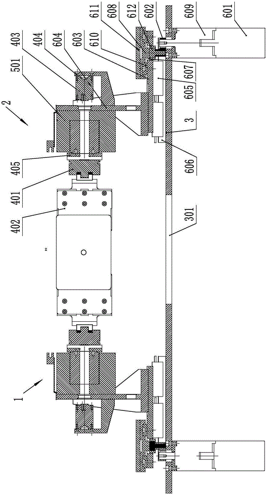
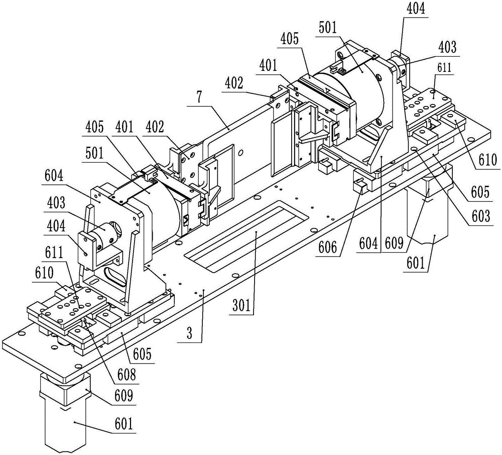
[0030] Such as figure 1 , 2 As shown, the present invention includes a laterally arranged fixing plate 3, and left and right winding heads 1 and 2 symmetrically arranged on the fixing plate 3. The left and right winding heads 1 and 2 both include a stack for clamping The clamping mechanism of the sheet 7, a rotating mechanism for reciprocating and intermittent rotation of 180 degrees, and a moving mechanism for driving the clamping mechanism forward or backward; the moving mechanism includes a moving motor 601 and an eccentricity driven by the moving motor 601 Parts, a sliding plate 603 connected to the eccentric part, and a fixing seat 604 connected to the sliding plate 603 that can drive the clamping mechanism to move left and right; the middle of the fixing plate 3 is provided with a diaphragm hole 301 for penetrating the diaphragm; when the moving motor 601 When rotating, the eccentric member connected to it rotates and drives the sliding plate 603 and the fixing base 604 to move left and right, and the clamping mechanism moves with the fixing base 604 left and right. In this technical solution, the eccentric member is driven by the rotation of the moving motor 601 to move the sliding plate 603 left and right to realize the forward and backward movement of the winding head. The action is fast and accurate, which is conducive to improving work efficiency and reliable.
[0031] In order to improve the flexibility of sliding and position the sliding, a slide rail seat 605 is provided under the slide plate 603, and the fixed plate 3 is provided with a slide plate guide rail 606 slidably connected to the slide plate guide seat 605. The slide rail seat 605 and the slide plate 603 are an integral structure or a separate assembly structure connected by a connector. In this technical solution, the slide rail seat 605 and the slide rail 606 form a sliding pair.
[0032] In order to increase the service life of the eccentric and improve the accuracy and reliability of the displacement, the eccentric includes a crankshaft 602 and a crankshaft follower 612. One end of the crankshaft 602 is a motor connection end, and the other end is a crankshaft follower connection end. The sliding plate 603 is provided with a sliding groove 607, the connecting end of the crankshaft follower of the crankshaft 602 is provided with a hole, and the lower part of the crankshaft follower 612 is inserted into the hole of the crankshaft 602. The crankshaft 602 is in an "L" shape, and its upper end is the sliding plate connecting end of the crankshaft follower. The crankshaft follower 612 covers the slider 608, and the slider 608 is slidingly connected to the sliding groove 607 The slider 608 is provided with a circular follower connecting hole with a downward opening, and the follower connecting hole is in clearance fit with the crankshaft follower 612. The crankshaft follower 612 is provided at the connecting end of the sliding plate, which can reduce friction and avoid the abrasion of the crankshaft 602, which is beneficial to increase the working life; and effectively avoids jams and other situations, and improves the reliability of work.
[0033] In order to improve the compactness of the structure, the sliding plate 603 includes a fixing base connecting part and a sliding block connecting part. The fixing base connecting part and the sliding block connecting part are arranged left and right, and the fixing base connecting part is closer to the lamination position than the sliding block connecting part. The diaphragm hole 301 of the fixing plate 3 is used for the lamination position of the lamination 7, the fixing base connecting part is used to connect the fixing base 604, the sliding block connecting part is used to connect the sliding block 608, and the fixing base connecting part is smaller than the sliding block connecting part. Being close to the stacking position can take into account the ease of assembly, reliability, and simplicity of the structure. At the same time, it is also conducive to reducing the volume, especially the length of the sliding plate 603, and improving the flexibility of sliding.
[0034] In order to improve the flexibility of sliding, reduce the sliding resistance. The slider connecting part is provided with the sliding groove 607, the left and right sides of the sliding groove 607 are provided with slider guide rails 610, the slider guide rail 610 is arranged in the front and rear direction, and the slider guide rail 610 is provided with a sliding connection with it The slider rail seat 611 is connected to the slider 608 through a connecting piece. The slider guide rail seat 611 can be an integral structure or a split structure.
[0035] In order to avoid movement interference, a deceleration device 609 is provided between the moving motor 601 and the crankshaft 602, and the moving motor 601 and the deceleration device 609 are arranged under the fixed plate 3. The moving motor 601 and the deceleration device 609 are arranged under the fixed plate 3, which is beneficial to reduce motion interference and reduce the volume.
[0036] In order to simplify the structure and improve the reliability of work, the rotating mechanism includes a rotating motor 501. The rotating shaft of the rotating motor 501 is a hollow shaft with a through hole in the middle. The clamping mechanism includes a clamping cylinder 401 and a clamping cylinder 401. Two pressing knives 402 arranged symmetrically in the front and rear driven by the holding cylinder 401, the air pipe of the holding cylinder 401 is connected to the air rotary joint 403 after passing through the through hole of the hollow shaft, and the rotating motor 501 is connected to the fixed seat 604, The rotating motor 501 and the clamping cylinder 401 are connected by a connecting piece 405.
[0037] The rotating motor 501 is a DD motor, and the fixing base 604 includes a vertical vertical plate for connecting with the rotating motor 501, a horizontal horizontal plate for connecting with the sliding plate 603, and The side plate, the vertical plate and the horizontal plate are connected to form an "L"-shaped connecting frame, the vertical plate of the connecting frame is located on the outside of the horizontal plate, and the outside of the connecting frame is provided with a gas rotary joint connecting frame 404. The air rotary joint connection frame 404 is provided with an air rotary joint, and the connecting frame is provided with a through hole opposite to the air rotary joint to pass through the air pipe. The connection frame has high strength and compact structure.
[0038] The lamination winding method includes the following steps:
[0039] 1) Initial preparation: the moving mechanism is at the outer position of the fixed plate 3, and the clamping mechanism is in an open state;
[0040] 2) Diaphragm clamping: The diaphragm passes through the diaphragm hole 301 from top to bottom, and the motor 601 for the movement of the left winding head 1 rotates 90° clockwise to drive the clamping mechanism of the left winding head 1 to move to the center of the lamination 7, while right The moving motor 601 of the winding head 2 rotates 90° counterclockwise and also drives the clamping mechanism of the right winding head 2 to move to the center of the lamination 7. After the respective movement distances are in place, the clamping mechanism on the left and right winding heads 2 The pressing knife 402 clamps the diaphragm at the same time;
[0041] 3) Stacked pole piece: There is a set of feeding components at the front and back of the center of the stack 7, and the positive and negative poles are pressed on both sides of the diaphragm on the above stacking position at the same time. After the pressure is released by the pair of press knives 402 of the left winding head 1 , The upper moving motor 601 rotates 90° clockwise to drive the pair of pressing knives 402 to move away from the center of the lamination 7, and at the same time, the pair of pressing knives 402 of the right winding head 2 do the same action, and move away from the center of the lamination 7 after the pressure is released. , After the respective movement distances are in place, move to the stack position, and clamp the diaphragm and pole piece assembly when in place;
[0042] 4) Winding: The DD motor of the left winding head 1 drives the press knife 402 to rotate 180° clockwise, while the DD motor of the right winding head 2 drives the press knife 402 to rotate 180° counterclockwise to drive the diaphragm pole piece assembly to rotate , And wrap the diaphragm on the outside of the positive and negative plates;
[0043] 5) Such a cycle, until the stacked pole pieces reach a certain thickness, the stack 7 is completed.
[0044] the above Figure 1-2 The shown winding head for a laminator and its working method are specific embodiments of the present invention, which have embodied the essential features and progress of the present invention. According to actual needs, under the enlightenment of the present invention, Equivalent modifications to its shape and structure are all within the scope of protection of this scheme.