Rotor self-circulation cooling system and cooling method for high-speed motor direct-drive turbomachinery

A technology of high-speed motors and turbomachinery, applied in the direction of cooling/ventilation devices, electromechanical devices, electrical components, etc., can solve the problems of inconspicuous cooling effect, large cooling air volume, and large circulation resistance, etc., and achieve the overall appearance, coordination and comprehensiveness of the unit Low energy consumption and low cooling energy consumption

Active Publication Date: 2017-05-10
SHANGHAI UNITED COMPRESSOR
View PDF7 Cites 7 Cited by
  • Summary
  • Abstract
  • Description
  • Claims
  • Application Information

AI Technical Summary

Problems solved by technology

[0006] 1. The external air source or fan needs power consumption, and the overall efficiency of the corresponding unit decreases
[0007] 2. The existence of structures such as cooling fans leads to the complexity of the overall structural design of high-speed motor direct-drive centrifugal compressors, especially for high-speed motor direct-drive centrifugal compressors with high power and high speed. The heat generated by the rotor is large, and the corresponding cooling air volume is large. , the fan structure is huge, which will destroy the coordination of the unit
[0008] 3. Since the gap between the rotor and the stator of the high-speed motor is very small, the amount of circulating cooling air is limited, and the cooling effect is not obvious, and the small gap between the motor stator and the rotor leads to a large flow resistance, and the overall cooling effect is not good.
[0009] In view of this, technicians in this field are committed to developing a rotor self-circulation cooling system of high-speed motor direct-drive turbomachinery to solve the problem of heat dissipation and cooling of the motor rotor and inner cavity of high-speed motor direct-drive turbomachinery

Method used


Image

  • Rotor self-circulation cooling system and cooling method for high-speed motor direct-drive turbomachinery
  • Rotor self-circulation cooling system and cooling method for high-speed motor direct-drive turbomachinery
  • Rotor self-circulation cooling system and cooling method for high-speed motor direct-drive turbomachinery

Examples


Embodiment Construction

[0032] The rotor self-circulation cooling system and cooling method of the high-speed motor direct-drive turbomachinery of the present invention will be described in detail below with reference to the drawings and embodiments.

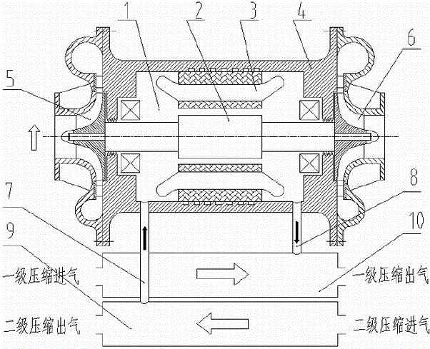
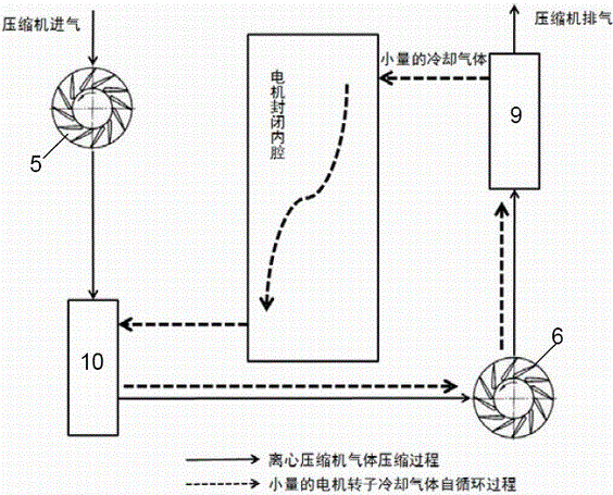
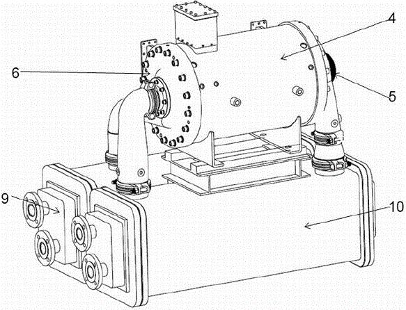
[0033] see figure 1 , the present invention provides a motor rotor self-circulation cooling system of a high-speed motor direct-drive centrifugal compressor, which is mainly composed of a motor closed casing 4, a high-speed motor inner cavity 1, a high-speed motor rotor 2, a motor stator coil 3, and a first-stage compressor 5 , secondary compression 6, rotor cavity cooling intake pipe 7, rotor cavity cooling outlet pipe 8, compressor primary cooler 10 and compressor secondary cooler 9.

[0034] The high-speed motor rotor 2 is arranged in the middle of the motor closed housing 4, and bearing seats and bearings are installed between the motor rotor 2 sides and the motor closed housing 4 inner walls. A motor stator coil 3 is installed on the periphery of...


PUM


Abstract

The invention relates to a rotor self-circulation cooling system and cooling method for a high-speed motor direct-drive turbomachinery. A motor rotor is arranged in the middle of the interior of a shell; a bearing pedestal and a bearing are mounted between the two sides of the motor rotor and the inner wall of the shell; a stator coil is arranged on the periphery of the motor stator; a motor inner cavity is formed in the internal space of the shell; a first-stage compressor is arranged at one end of the shell while a second-stage compressor is arranged at the other end of the shell; a rotor inner cavity cooling air inlet pipe and an air outlet pipe are arranged on the shell separately; and the air inlet pipe is connected with a compressor second-stage cooler while the air outlet pipe is connected with a compressor first-stage cooler. A little cooling gas enters the motor inner cavity from the second-stage cooler to take away heat of the motor rotor, and then enters the first-stage cooler to be cooled and to be compressed through the second-stage compressor, and then enters the second-stage cooler to be cooled and then enters the motor inner cavity so as to complete the self-circulation process of a little motor rotor cooling gas. By virtue of the rotor self-circulation cooling system and cooling method, the heat exchange efficiency can be improved; the comprehensive energy consumption is low; and parts of an external air source, a cooling fan and the like are not required in the cooling process.

Description

technical field [0001] The present invention relates to the rotor self-circulation cooling method of high-speed motor direct-driven turbomachinery (including centrifugal compressor, refrigeration compressor, MVR steam compressor, waste heat recovery expander, chemical medium compressor, etc.), especially a high-speed A high-speed motor direct-drive turbomachinery, such as a rotor self-circulation cooling system of a centrifugal compressor, and a cooling method. Background technique [0002] The high-speed motor direct-drive turbomachinery integrates the motor function and gear speed-up transmission structurally. The high-speed motor spindle directly drives the turbine impeller, and the rotor is supported by electromagnetic suspension bearings or air suspension bearings. The heating of high-speed motors is mainly divided into stator coil heating and rotor heating. The heating problem of the stator coil of the motor can basically be solved by stator water cooling, while the he...

Claims


Application Information

Patent Timeline
Patent Type & Authority Applications(China)
IPC IPC(8): H02K1/32H02K9/04
CPCH02K1/32H02K9/04
Inventor 林伟伟张回良崔小健李伟莫婷婷
Owner SHANGHAI UNITED COMPRESSOR
Why Eureka
Try Eureka