

High-speed permanent magnet motor rotor structure
A permanent magnet motor and rotor structure technology, applied in the direction of magnetic circuit shape/style/structure, magnetic circuit rotating parts, etc., can solve the problems of repulsive force generated by permanent magnets, difficult to fit tooling, etc., to avoid broken, convenient tooling difficulty , The effect of convenient finishing
- Summary
- Abstract
- Description
- Claims
- Application Information
AI Technical Summary
Problems solved by technology
Method used
Image

Examples
Embodiment Construction
[0018] The present invention will be further described below in conjunction with the accompanying drawings and embodiments.
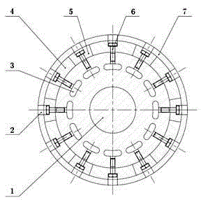
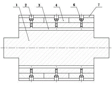
[0019] Such as figure 1 , 2, the rotor structure of the high-speed permanent magnet motor of the present invention includes a rotor 1, a permanent magnet block 4, a magnetic pole interval 5, a bolt 6, a sheath 7, and the like.
[0020] There are radial bolt holes 2 and axial ventilation holes 3 on the rotor 1, and the two are connected. The permanent magnet block 4 and the magnetic pole spacer 5 also have bolt holes, and the permanent magnet block 4 and the magnetic pole spacer 5 are fixed on the rotor 1 by bolts 6 . At this time, the entire rotor 1 can be finished with the outer circle of the rotor to reduce the fit tolerance, improve its concentricity, and ensure the dynamic balance of the rotor at high speed.
[0021] The sheath 7 is made of high-strength metal such as titanium alloy or steel, and has holes corresponding to rotor bolts on it, and i...
PUM
 Abstract
Description
Claims
Application Information