

Conductive liquid micro driving device and applications thereof
A conductive liquid and driving device technology, applied in electromechanical devices, electrical components, etc., can solve the problems of high processing cost, complex structure, and reduced motor efficiency, and meet the requirements of reducing the use environment, compact overall structure, and save installation space. Effect
- Summary
- Abstract
- Description
- Claims
- Application Information
AI Technical Summary
Problems solved by technology
Method used
Image

Examples
Embodiment 1
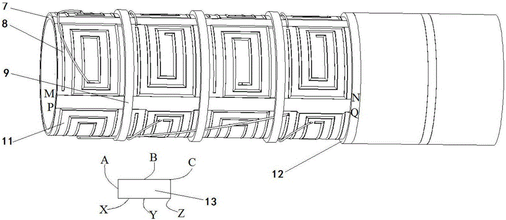
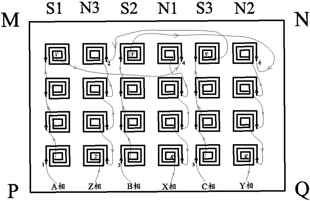
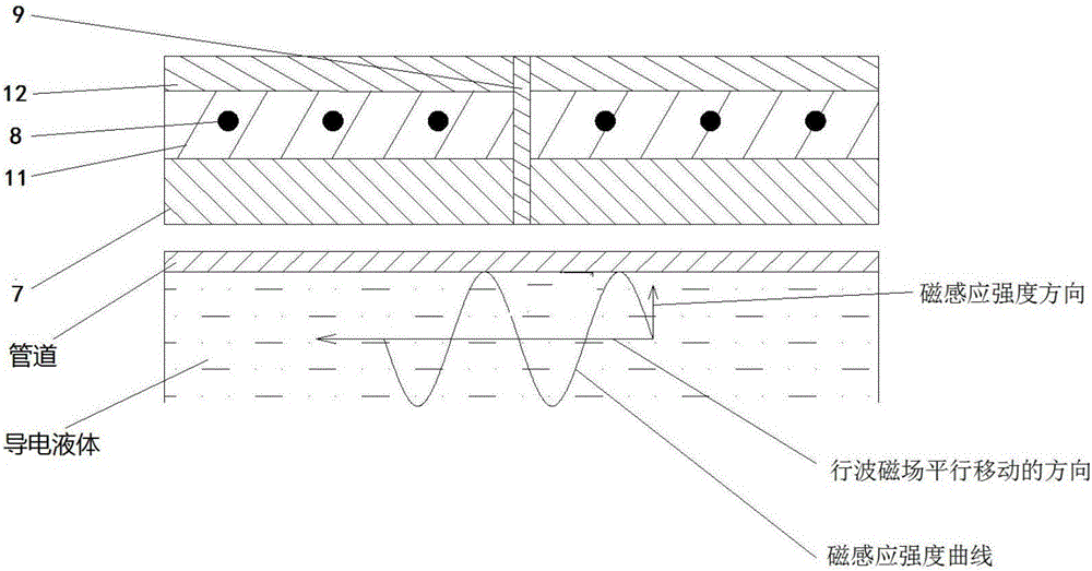
[0050] In this example, see Figure 1~4 , a conductive liquid micro-drive device, including a flexible substrate 7, a rectangular coil 8, an insulating layer 9, a magnetically permeable layer 11, a cover 12 and an inverter 13, the flexible substrate 7 is made of an insulating flexible material, and has good flexibility , which can meet the needs of complex deformation. The back of the flexible substrate 7 forms an installation junction, and the outer wall of the tube is used as the installation part to fix and combine the back of the flexible substrate 7 with the outer wall of the tube. On the front of the flexible substrate 7, from bottom to top The magnetic permeable layer 11 and the cover 12 are set, and k×j rectangular coils 8 are used to form a coil array, wherein the number of rows k=4, the number of columns j=6, and an insulating layer 9 is set between any adjacent rectangular coils 8, each An insulating layer 9 is also arranged between the circular wires of each rectan...
Embodiment 2
[0071] This embodiment is basically the same as Embodiment 1, especially in that:
[0072] In this example, see Figure 5 , an application of a conductive liquid micro-drive device, the flexible conductive liquid micro-drive device is coated on the outside of the pipeline of the bioconductive liquid to form an electromagnetically driven pump for the bioconductive liquid, the pipeline of the bioconductive liquid is a blood vessel, and the bioconductive liquid is Blood, by controlling the conductive liquid micro-drive device, drives the conductive liquid in the pipeline of the bioconductive fluid to flow, thereby reducing the adhesion of the bioconductive liquid to the wall of the bioconductive fluid, and preventing the deposits on the inner wall of the pipeline of the bioconductive fluid or Accelerated dissolution treatment of attachments, by changing the magnitude, phase or frequency of the multiphase current applied by the conductive liquid micro-drive device, to control the ...
Embodiment 3
[0076] This embodiment is basically the same as the previous embodiment, and the special features are:
[0077] see Figure 6 , the present embodiment adopts 3 flexible driving devices, and the installation parts on the back of the flexible substrate 7 of the 3 flexible driving devices are respectively coated on the outside or inside of the 3 branch pipes (10, 20, 30), and the 3 branch pipes ( 10, 20, 30) respectively input three kinds of conductive liquids, control the time, phase, size, direction, and frequency parameters of the input currents of the three inverters 13, generate traveling wave magnetic fields that meet the requirements, and obtain different sizes and directions Electromagnetic force pushes the conductive liquid in the three branch pipes (10, 20, 30) to flow in the same direction or in the opposite direction at the speed v1, v2 and v3 respectively, and v1+v2+0, v1+v2+v3 are obtained in the main pipe 40 , 0+v2+v3, -v1+v2+v3, v1+0+v3, v1-v2+v3, v1+0-v3, v1+v2-...
PUM
 Abstract
Description
Claims
Application Information