
Constant-power LED driving system and constant-power control method

A LED driving, constant power technology, applied in the use of semiconductor lamps, electrical components, electroluminescent light sources, etc., can solve the problems of being susceptible to interference, maintaining constant, high negative voltage, etc.

Active Publication Date: 2017-05-10
SHANGHAI SIMAX TECH CO LTD
View PDF4 Cites 3 Cited by
  • Summary
  • Abstract
  • Description
  • Claims
  • Application Information

AI Technical Summary

Problems solved by technology

From the perspective of semiconductors, light-emitting diodes have the volt-ampere characteristics of ordinary diodes, that is, after a forward conduction voltage is applied across the light-emitting diode, a very small voltage change can cause a large change in the current flowing through the light-emitting diode: For example, when the forward conduction voltage of the light emitting diode is about 3.00V, the current flowing through the light emitting diode is about 350mA; when the forward conduction voltage of the light emitting diode is 3.25V, the current flowing through the light emitting diode is about 750mA, Through a simple comparison, it can be seen that although the forward voltage of the light-emitting diode has only slightly changed by a small 250mV, the current flowing through the light-emitting diode has more than doubled, and the light-emitting diode has a higher negative voltage. / temperature coefficient, so the constant voltage power supply cannot guarantee that the LED current remains unchanged as expected, which undoubtedly affects the luminous effect of the LED, because the light radiation intensity of the LED is related to the current flowing through it
Although the constant current power supply can make the LED lamps work stably, due to the influence of the ambient operating temperature, the working voltage at both ends of the LEDs is not the same, and the power of the LED lamps also changes accordingly, so the brightness of the LEDs cannot be adjusted. get the best out of
Therefore, the existing constant voltage or constant current driving methods for LED lamps cannot effectively solve the problems caused by the power of LEDs changing with temperature and operating voltage of LEDs. The industry needs to propose a better constant power control method for LED lamps
[0003] Based on the constant power scheme of some current drive circuit architectures, because sometimes the actual peak value of the AC mains is slightly larger than the expected peak value, or the line voltage at a certain moment is larger than the conventional preset voltage value at that moment, the result is: When the line voltage supplied to the LED string is too high, the total current waveform flowing through the LEDs will show a sag at the moment corresponding to the high line voltage. The higher the line voltage drifts, the higher the sag characteristic of the total current will be. The deeper it is, the moment when the line voltage is too high, that is, when the total current is depressed, can make the input power basically constant, but it will cause the waveform of the total current to deviate from the sinusoidal curve, and it is easy to be disturbed at the depression, which will make the power factor and total harmonic distortion indicators have seriously deteriorated

Method used


Image

  • Constant-power LED driving system and constant-power control method
  • Constant-power LED driving system and constant-power control method
  • Constant-power LED driving system and constant-power control method

Examples


Embodiment Construction

[0041] In the following, the technical solutions of the present invention will be clearly and completely described in conjunction with various embodiments. However, the described embodiments are only the embodiments used for the description of the present invention and not all the embodiments. Based on these embodiments, the present invention The solutions obtained by those skilled in the art without creative work all fall within the protection scope of the present invention.

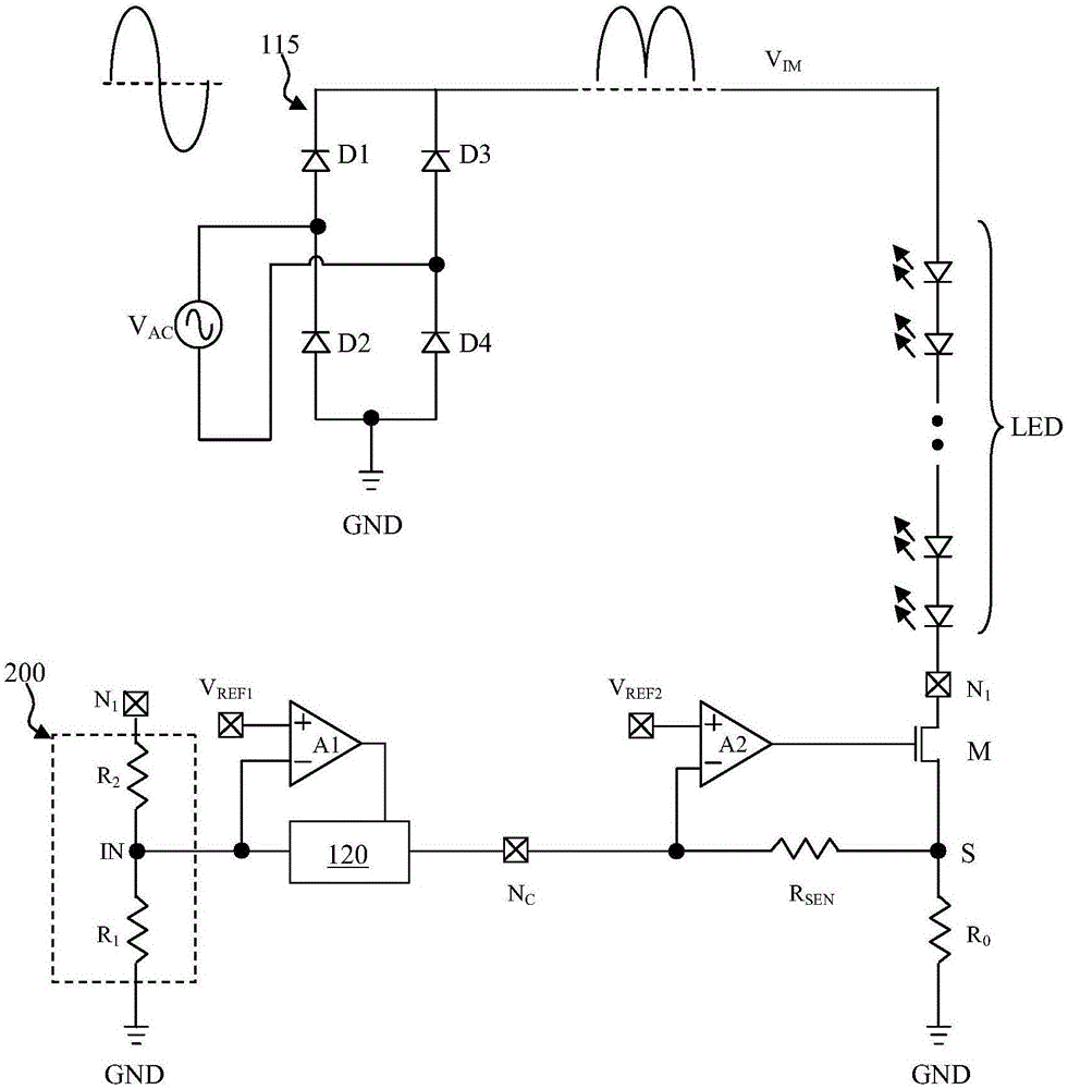
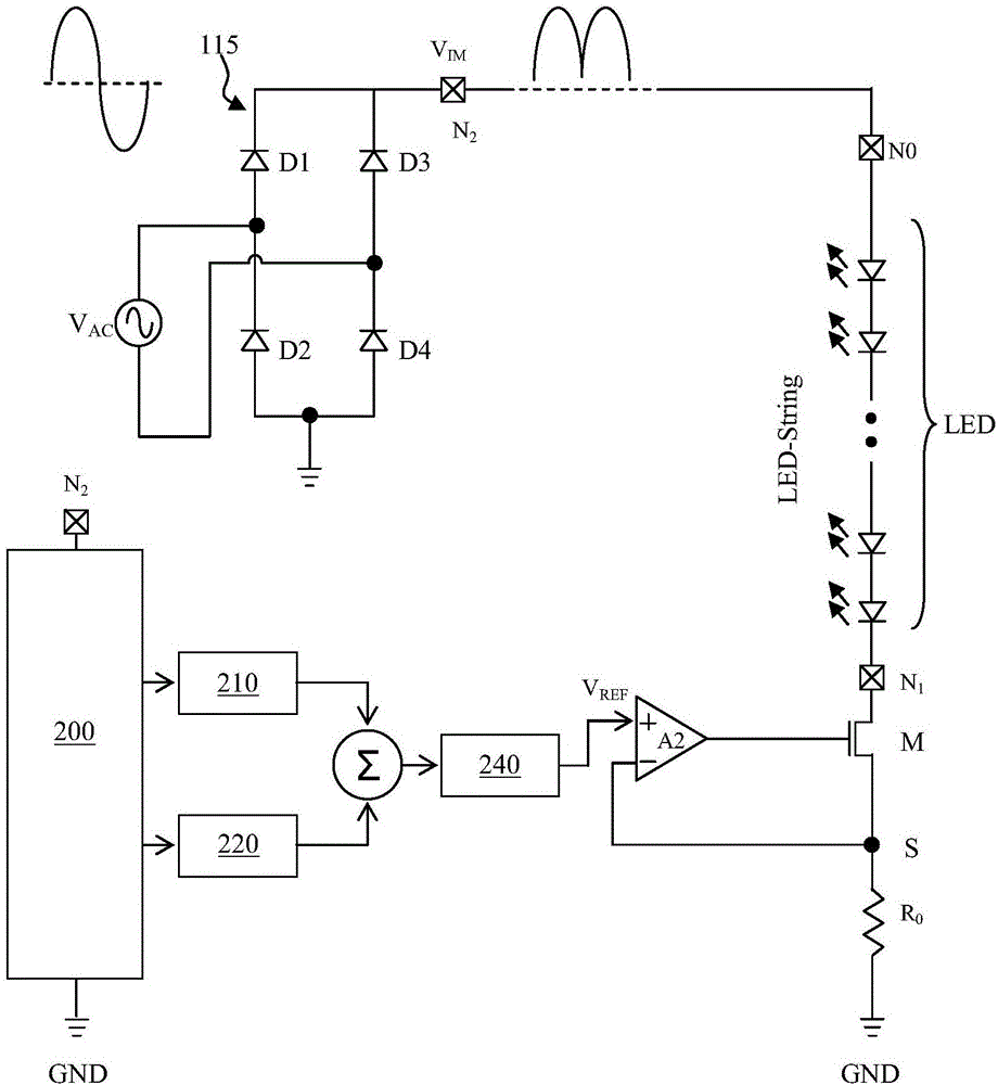
[0042] See figure 1 , Is the basic topology of the constant power control circuit, AC mains V AC From AC grid, AC mains V AC Full-wave rectification is performed by the bridge rectifier 115. The bridge rectifier 115 has four diodes D1-D4 and belongs to the prior art. The voltage output by the bridge rectifier 115 is a fluctuating pulsating voltage V IM . Pulsating voltage V IM It is used to supply power to the series of light-emitting diode strings. The cathode of the former diode in the series of diod...


PUM


Abstract

The invention mainly relates to a constant-power LED driving system and a constant-power control method. A driving system for driving an LED string group is provided in a topological structure comprising an LED string group; the constant-power LED driving system comprises a main transistor connected with the LED string group in series and a current sensing resistor; an alternating current is rectified by a bridge type rectifier to generate a pulsating voltage to supply power to the LED string group; a provided reference voltage is input at the positive phase end of a first operational amplifier; the total current waveform, which flows through the LED string group, can be close to sine wave under a constant power condition, so that it is ensured that the input power still can be maintained at a basically constant mode when the voltage provided to the LED string group is in an overhigh condition; and relatively high power factor / total harmonic distortion index is achieved.

Description

Technical field [0001] The present invention mainly relates to the field of energy-saving lighting. Specifically, it relates to providing a driving system for driving the LED string in the topological structure of the LED string containing light-emitting diodes, so that the LED string can flow through the LED string under the condition of constant power. The total current waveform is close to a sine wave, which ensures that the voltage provided to the LED string group can still maintain the input power in a basically constant mode under excessively high conditions, and has a good power factor / total harmonic distortion index. Background technique [0002] After the use of LED lamps in the lighting field, LED lamps are increasingly being valued by countries around the world, especially in countries and regions with energy shortages, because they have high luminous efficiency, obvious energy-saving effects, long life, pollution-free, and anti-vibration. This demand is even stronger....

Claims


Application Information

Patent Timeline
Patent Type & Authority Applications(China)
IPC IPC(8): H05B33/08H05B44/00
CPCH05B45/00Y02B20/30
Inventor 高智浩刘慧博许明伟吕洪博
Owner SHANGHAI SIMAX TECH CO LTD
Learn More