
Resonator circuit

A resonator, circuit technology, used in power oscillators, amplifiers, electrical components, etc.

Active Publication Date: 2017-05-10
HUAWEI TECH CO LTD
View PDF3 Cites 5 Cited by
  • Summary
  • Abstract
  • Description
  • Claims
  • Application Information

AI Technical Summary

Problems solved by technology

However, phase noise performance in the 20dB / decade region degrades especially at low supply voltage and high current consumption

Method used


Image

  • Resonator circuit
  • Resonator circuit
  • Resonator circuit

Examples


Embodiment Construction

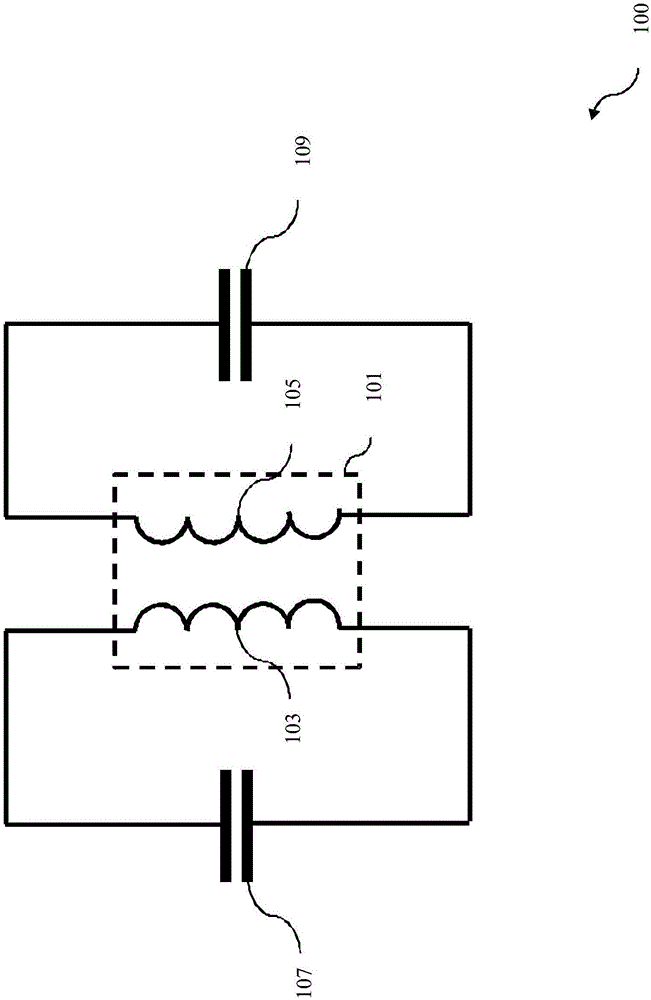
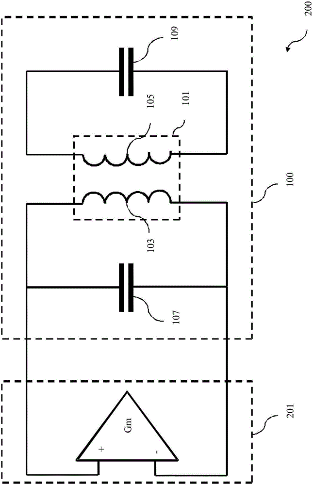
[0054] figure 1 A diagram of a resonator circuit 100 according to an embodiment is shown. The resonator circuit 100 comprises a transformer 101 comprising a primary winding 103 and a secondary winding 105, wherein the primary winding 103 is inductively coupled to the secondary winding 105, a primary capacitor 107 is connected to the primary winding 103, the primary capacitor 107 and the primary winding 103 forms the primary circuit, and the secondary capacitor 109 is connected to the secondary winding 105, the secondary capacitor 109 and the secondary winding 105 form the secondary circuit, wherein the resonator circuit 100 has a common mode when the primary circuit is excited in the common mode A resonant frequency, wherein the resonator circuit 100 has a differential mode resonant frequency when the primary circuit is excited in the differential mode, and wherein the common mode resonant frequency is different from the differential mode resonant frequency. In an embodiment,...


PUM


Abstract

The invention relates to a resonator circuit (100), the resonator circuit (100) comprises a transformer (101) comprising a primary winding (103) and a secondary winding (105), wherein the primary winding (103) is inductively coupled with the secondary winding (105), a primary capacitor (107) being connected to the primary winding (103), the primary capacitor (107) and the primary winding (103) forming a primary circuit, and a secondary capacitor (109) being connected to the secondary winding (105), the secondary capacitor (109) and the secondary winding (105) forming a secondary circuit, wherein the resonator circuit (100) has a common mode resonance frequency at an excitation of the primary circuit in a common mode, wherein the resonator circuit (100) has a differential mode resonance frequency at an excitation of the primary circuit in a differential mode, and wherein the common mode resonance frequency is different from the differential mode resonance frequency.

Description

technical field [0001] The present invention relates to the field of radio frequency (radio frequency, RF) resonator circuits. Background technique [0002] Resonator circuits, also denoted tank circuits, are widely used as frequency selective elements in a variety of radio frequency components, such as filters, amplifiers and oscillators. Typically, a resonator circuit includes an inductor and a capacitor connected to resonate at a particular resonant frequency. The quality of the resonator circuit is thus characterized as a quality factor. The characteristics of resonator circuits are of major concern in the design of radio frequency oscillators, especially when they are implemented as radio frequency integrated circuits (RFICs) on semiconductor substrates. In particular, the response of a resonator circuit with respect to leakage currents or currents at harmonic frequencies can have a major impact on the frequency stability and phase noise performance of a radio frequen...

Claims


Application Information

Patent Timeline
IPC IPC(8): H03B5/12
CPCH03B5/1218H03B5/1228H03B5/1243H03B5/1262H03B5/1296H03B2201/0266H03B5/1293H03F1/565H03B5/124H03F3/193H03L7/00H04B1/44H03B5/1265
Inventor 米娜·沙赫莫哈马迪马苏德·巴贝耶罗伯特·斯塔泽夫斯基
Owner HUAWEI TECH CO LTD
Learn More