Spraying method for coating on inner wall of pipeline

A technology for pipelines and coatings, which is applied in the direction of coatings and devices for coating liquid on the surface, etc., which can solve the problems of difficulty in changing the diameter of spraying devices, increasing processing costs, and difficulties in the anti-corrosion and anti-oxidation of the inner wall of the pipeline, etc., to achieve reduction The loss of kinetic energy, the reduction of friction, the effect of strong centrifugal action

Active Publication Date: 2017-05-17
CHONGQING YONGCHUAN DISTRICT TAIXING MACHINERY FACTORY
View PDF6 Cites 15 Cited by
  • Summary
  • Abstract
  • Description
  • Claims
  • Application Information

AI Technical Summary

Problems solved by technology

[0003] At present, the anti-corrosion and anti-oxidation treatment of steel pipelines is divided into external surface treatment and pipeline inner wall treatment. The anti-corrosion treatment of the outer surface of the pipeline is relatively convenient and simple, but the anti-corrosion and anti-oxidation treatment of the inner wall of the pipeline will be more difficult, mainly because The length of the pipe is long, and the spraying device needs to be made long enough, and the diameter of the inner ring of the pipe will also change when the pipe is different, but the diameter of the spraying device is difficult to change, which will easily lead to the need to use different pipes when painting different pipes. Different coating devices, increased processing costs

Method used


Image

  • Spraying method for coating on inner wall of pipeline
  • Spraying method for coating on inner wall of pipeline
  • Spraying method for coating on inner wall of pipeline

Examples


Embodiment Construction

[0021] The present invention will be described in further detail below by means of specific embodiments:

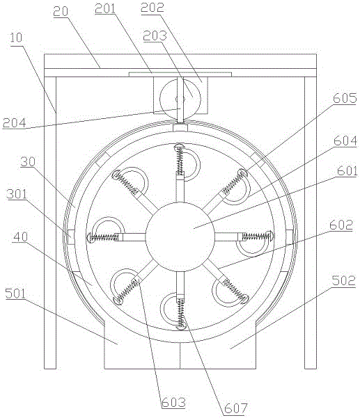
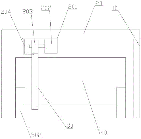
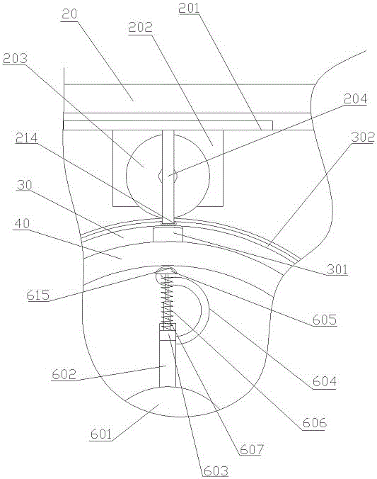
[0022] The reference signs in the accompanying drawings include: frame 10, servo mechanism 20, moving block 201, motor 202, driving gear 203, push rod 204, ball 214, driven gear 30, first magnet 301, chute 302, Pipeline 40, left fixing clip 501, right fixing clip 502, paint containing box 601, branch pipe 602, slider 603, bellows 604, second magnet 605, sponge 615, connecting rod 606, spring 607.

[0023] The embodiment is basically as attached figure 1 , attached figure 2 And attached image 3 Shown: a magnetic spraying device, including a frame 10, a clamp for fixing the pipeline 40, a driving gear 203, a motor 202, a coating device arranged in the pipeline 40, and a driven gear 30 capable of meshing with the driving gear 203 . The fixing clip is horizontally arranged directly below the frame 10, and a servo mechanism 20 is installed on the top of the frame 10. The...


PUM


Abstract

The invention relates to the field of surface treatment, and particularly discloses a spraying method for a coating on the inner wall of a pipeline. According to the spraying method, a magnetic spraying device is adopted, and a coating device in the magnetic spraying device is placed in the pipeline; a first magnet mounted on a driven gear can attract a second magnet, a connecting rod connected with the second magnet is pulled at the same time, a sliding block is made to move in a branch pipe, a discharging port between the branch pipe and a corrugated pipe is not blocked any more in the moving process of the sliding block, and paint in a paint storage box can flow into a storage cavity of the second magnet accordingly; and when the driven gear rotates, the second magnet is driven to rotate at the same time, the whole coating device is made to rotate accordingly, paint in the coating device flows out from a spraying port of the second magnet under the effect of centrifugal force in the rotating process and then is sprayed onto the inner wall of the pipeline, and the inner wall of the pipeline is coated. By adoption of the scheme, the inner wall of the pipeline can be sprayed.

Description

technical field [0001] The invention belongs to the field of surface treatment, and in particular relates to a spraying method. Background technique [0002] The pipes on ships are mostly made of steel, but the pipes made of steel contain a lot of iron; when the ship is operating at sea for a long time, due to the high humidity and high salinity of the sea breeze, the iron in the pipe and the sea breeze The redox reaction occurs in the salt and alkali, causing the pipeline to be eroded by the sea breeze. When the pipeline is directly immersed in seawater, the seawater phase will directly act as an electrolyte solution, causing the pipeline to be corroded after an electrochemical reaction occurs, so the pipeline immersed in seawater is more likely to be corroded. [0003] At present, the anti-corrosion and anti-oxidation treatment of steel pipelines is divided into external surface treatment and pipeline inner wall treatment. The anti-corrosion treatment of the outer surface...

Claims


Application Information

Patent Timeline
Patent Type & Authority Applications(China)
IPC IPC(8): B05D7/22B05C7/08B05C13/02
Inventor 唐正权
Owner CHONGQING YONGCHUAN DISTRICT TAIXING MACHINERY FACTORY
Why Eureka
Try Eureka