Buckling induction support with ends provided with annular Y-shaped induction units

A ring-direction and sub-unit technology, applied in building types, building components, earthquake resistance, etc., can solve the problems of low design flexibility and unfavorable plastic hinges, simplify the manufacturing process, reduce the workload of wet work, and achieve structural type simple effect

Active Publication Date: 2017-05-17
SOUTHEAST UNIV
View PDF8 Cites 0 Cited by
  • Summary
  • Abstract
  • Description
  • Claims
  • Application Information

AI Technical Summary

Problems solved by technology

On June 1, 2016, the applicant proposed an energy-dissipative buckling-constrained support with symmetrical initial defect units at the end (application number 201610383430.5) and a buckling-controlled support with diamond-shaped energy-dissipating units at the end (application No. 2016103808

Method used


Image

  • Buckling induction support with ends provided with annular Y-shaped induction units
  • Buckling induction support with ends provided with annular Y-shaped induction units
  • Buckling induction support with ends provided with annular Y-shaped induction units

Examples


Example Embodiment

[0024] The present invention will be further explained below in conjunction with the drawings.

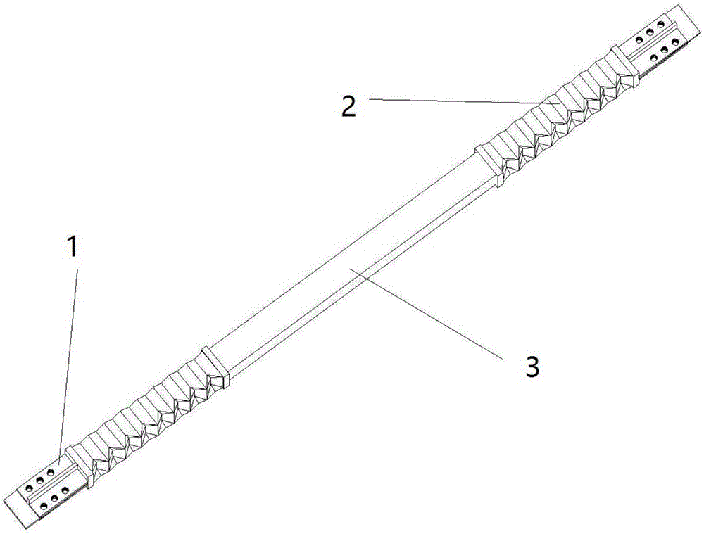
[0025] figure 1 It is a structural schematic diagram of a buckling-inducing support with a circular Y-shaped inducing element at the end. It is composed of an end restraint section 1, an energy dissipating section 2 and a straight support section 3. The end restraining section 1 is fixed at the beam-column node and the energy dissipation Between the sections 2, the energy-consuming section 2 is fixed at both ends of the supporting straight section 3.

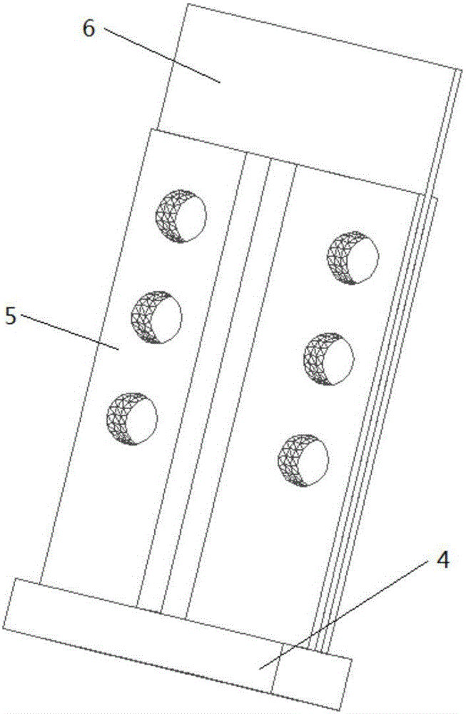
[0026] Such as figure 2 As shown, the end restraint section 1 is composed of a square steel plate 4, a T-shaped short steel beam 5, and a connecting plate 6 reserved for beams and columns. The square steel plate 4 is welded to the end of the energy dissipating section 2. Two T-shaped short steel Beam 5 is welded to square steel plate 4, square steel plate 4 and T-shaped short steel beam 5 are respectively shown Figure 5 , 6 Shown. The ...


PUM


Abstract

The invention discloses a buckling induction support with the ends provided with annular Y-shaped induction units. The buckling induction support comprises constraining sections, energy consumption sections and a supporting straight section. The energy consumption sections are arranged at the two ends of the supporting straight section and each composed of at least one annular Y-shaped induction unit in the axial direction of the support. Each annular Y-shaped induction unit is a space body which is formed by sequentially arranging m annular Y-shaped sub units in the annular direction, and the section of the space body is a regular m polygon. Each annular Y-shaped sub unit is a space body formed by collinearly folding two triangular plates and two trapezoidal plates located in the same plane correspondingly in pair. The buckling induction support keeps elasticity under the effect of small earthquakes, enters a yielding stage under the effect of medium earthquakes or large earthquakes, and can achieve the effect of a damper by means of the good hysteretic energy consumption performance of the support. Compared with traditional buckling constraint supports, by adoption of the buckling induction support, the workload of site construction operation is decreased, energy is saved, and the environment is protected.

Description

technical field [0001] The invention belongs to the technical field of building structures, and in particular relates to a buckling induction support with a circumferential Y-shaped induction unit at the end, which is suitable for steel structures or concrete structures with buckling restraint supports. Background technique [0002] During the use of steel structures or reinforced concrete structures, ordinary supports will buckle under compression. When the supports buckle under compression, the stiffness and bearing capacity will decrease sharply. Under the action of earthquake or wind, the internal force of the support changes back and forth under the two states of compression and tension. When the support gradually changes from the buckling state to the tension state, the internal force and stiffness of the support are close to zero. Therefore, the hysteretic performance of ordinary supports is poor under repeated loads. In order to solve the problem of buckling under ...

Claims


Application Information

Patent Timeline
IPC IPC(8): E04H9/02E04B1/98
CPCE04H9/021
Inventor 蔡建国冯健叶震周宇航柳杨青马瑞君
Owner SOUTHEAST UNIV
Why Eureka
Try Eureka