
A counter-type flame-resisting component and a flame-resisting explosion-proof valve

A hedging type, explosion-proof valve technology, applied in the direction of engine components, machines/engines, mechanical equipment, etc., can solve the problem of unable to extinguish the flame, and achieve the effect of protecting equipment

Active Publication Date: 2022-05-24
谢函
View PDF13 Cites 0 Cited by
  • Summary
  • Abstract
  • Description
  • Claims
  • Application Information

AI Technical Summary

Problems solved by technology

This kind of explosion-proof valve can make the explosive air flow more uniformly dispersed by the diversion hole, but it cannot completely extinguish the flame in the explosion-proof valve.

Method used


Image

  • A counter-type flame-resisting component and a flame-resisting explosion-proof valve
  • A counter-type flame-resisting component and a flame-resisting explosion-proof valve
  • A counter-type flame-resisting component and a flame-resisting explosion-proof valve

Examples


Embodiment 1

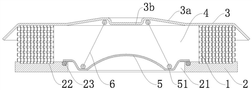
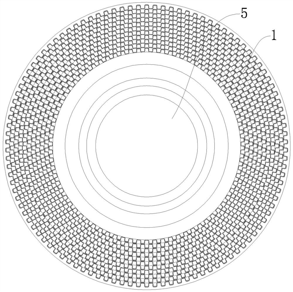
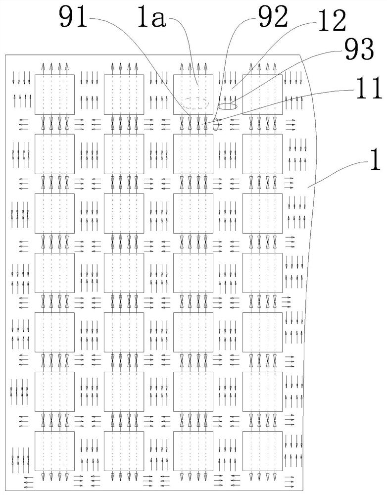
[0027] The hedging type flame arrester assembly in this embodiment includes at least three layers of annular flame retardant sheets 1 that are coaxially nested. Each layer of flame retardant sheet 1 has an annular body composed of elongated sheet bodies connected end to end, and bosses 1a protruding radially outward are formed on the annular body at intervals. There are transverse airflow channels 11 and vertical airflow channels 12 between adjacent bosses 1a. The side wall of each boss 1a has at least one through hole 13 penetrating the annular body.

[0028] Each boss 1a is provided with corresponding through holes 13 on opposite sides. The airflow comes out from the through holes 13 on both sides of the boss 1a. Since the through holes 13 of the adjacent bosses 1a are opposite to each other, the flames sprayed from the through holes 13 of the two adjacent bosses 1a can form a positive hedge.

[0029] The bottom of the boss 1a is an arc surface 1b. The bottom of the boss ...

Embodiment 2

[0040] The difference between Embodiment 2 and Embodiment 1 is that each boss 1a is provided with through holes 13 in the same direction on the same side. like Image 6 As shown, since only one side of each boss 1a is provided with a through hole 13, the through hole 13 faces the wall surface of the adjacent boss 1a. After the explosion, the flame first collides and refracts with the wall surface of the first layer of flame retardant sheet 1 to change the direction of the flame, resulting in the first loss of flame energy. Then the flame escapes from the through hole 13 on one side of the boss 1a to form a flame 91. The flame 91 collides with the wall surface of the adjacent boss 1a to cause a second energy loss, and changes direction to form a flame 92. Between the bosses 1a and the front and rear two layers of flame retardant sheets 1 form a transverse airflow channel 11 to hedge, resulting in a third flame energy loss and a reduction in the propagation speed. After the flam...


PUM


Abstract

The invention discloses a counter-type flame-resisting component and a flame-resisting explosion-proof valve. The counter-type flame-resisting component comprises at least three layers of ring-shaped flame retardant sheets that are coaxially nested. The flame retardant sheet of each layer has an annular body composed of elongated sheet-shaped bodies connected end to end, and bosses protruding radially outward are formed at intervals on the annular body. There are horizontal airflow passages and vertical airflow passages between adjacent bosses. The side wall of each boss has at least one through hole penetrating through the ring body. In the present invention, several layers of flame retardant sheets are used to form a hedging type flame retardant assembly, and the convex structure on the flame retardant sheet and the relative through hole are used to make the flame generated by the explosion perform hedging action and wall collision for many times. After several times of hedging and collision, the energy is greatly lost, and it can be quickly extinguished and released as hot gas, which plays a role in protecting the equipment.

Description

technical field [0001] The invention relates to an explosion-proof valve of a diesel engine, in particular to a hedging type flame arrester assembly and a flame arrester type explosion-proof valve. Background technique [0002] Diesel engine is a very complex moving machine. When it is running, internal running parts such as crankshaft, cylinder liner and piston will generate a lot of heat due to mutual friction. These friction and heat require the oil in the crankcase to lubricate and lubricate. cooling, resulting in a large amount of oil and gas. In some extreme cases, the friction pair between them will bite due to poor coordination, which is commonly referred to as the crankshaft pad, the piston cylinder liner pulling the cylinder, which will generate a lot of heat, which is enough to ignite the oil and gas, As a result, the crankcase exploded. [0003] In order to prevent damage from accidents, the International Maritime Organization requires diesel engines to be equi...

Claims


Application Information

Patent Timeline
Patent Type & Authority Patents(China)
IPC IPC(8): F02B77/10
CPCF02B77/10
Inventor 谢函
Owner 谢函
Learn More