Cooling ventilator for locomotive traction transformer

A traction transformer, cooling and ventilation technology, applied in the direction of transformer/inductor cooling, machine/engine, transformer/inductor parts, etc., can solve the problems that cannot meet the flow requirements of locomotive traction transformers, and achieve convenient manufacturing, installation and maintenance, and use Convenience and the effect of reducing the weight of the structure

Active Publication Date: 2017-05-17
ZHUZHOU LINCE GRP
View PDF9 Cites 0 Cited by
  • Summary
  • Abstract
  • Description
  • Claims
  • Application Information

AI Technical Summary

Problems solved by technology

The ventilator with this structure still cannot meet the

Method used


Image

  • Cooling ventilator for locomotive traction transformer
  • Cooling ventilator for locomotive traction transformer
  • Cooling ventilator for locomotive traction transformer

Examples


Example Embodiment

[0027] The following describes the embodiments of the present invention in detail with reference to the accompanying drawings, but the present invention can be implemented in a variety of different ways defined and covered by the claims.

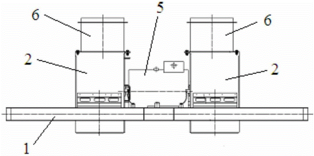
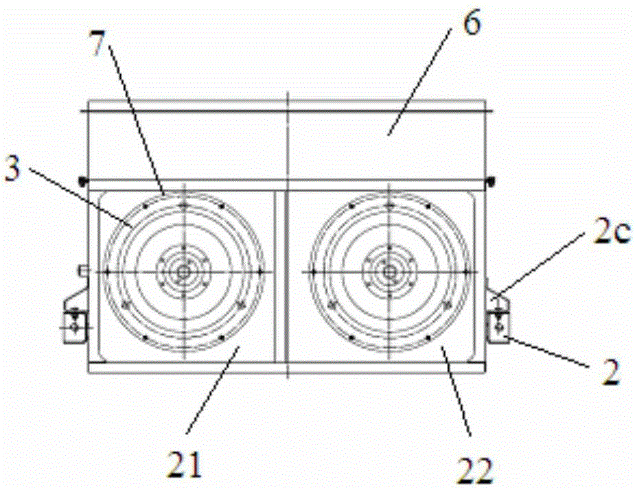
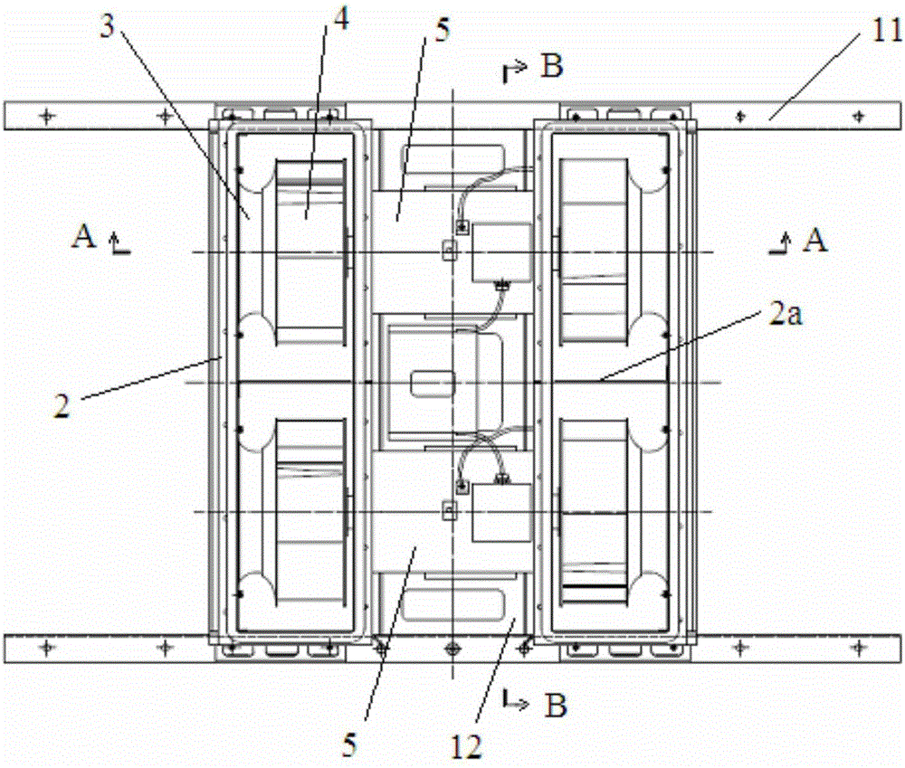
[0028] See Figure 1 to Figure 5 , The cooling fan for locomotive traction transformer of the present invention includes a mounting frame 1, two boxes 2, four air inlets 3, four centrifugal impellers 4, and two double-outlet shaft motors for driving the impellers to rotate 5 and the air outlet 6 arranged on the top of the box body for the gas to be discharged from the bottom to the top. The mounting frame includes an I-beam structure. The I-beam includes two parallel beams 11 and a connecting beam 12, and two double output shaft motors Both are installed on the connecting beam. The motor shafts 51 of the two double-out shaft motors are arranged in parallel with the parallel beam. Each double-out shaft motor is connected with two left and right ...


PUM


Abstract

The invention provides a cooling ventilator for a locomotive traction transformer. The cooling ventilator comprises a mounting rack, two boxes, air inlets, impellers, two output-shaft motors and an outtake, wherein the two output-shaft motors are mounted on a connecting beam of the mounting rack; each of the two output-shaft motors is connected with the left impeller and the right impeller; the two boxes are used for accommodating the left impeller and the right impeller connected onto the two output-shaft motors; a partition board for partitioning each box into a front box and a rear box is arranged in each box; an air inlet mounting plate for fixing each air inlet is arranged on the air inlet side of each box and is connected with the side wall of the air inlet side of the corresponding box; the front end and rear end of each box are connected with a parallel beam of the mounting rack; and a mounting hole for allowing a motor shaft to stretch into the corresponding box is formed in a motor mounting side of the corresponding box. According to the cooling ventilator for the locomotive traction transformer, the two motors and the two boxes are directly mounted on the same mounting rack, so that the structure is simple and compact, the manufacture, installation and maintenance are convenient, the size is small and the flow rate is large.

Description

technical field [0001] The invention relates to the technical field of cooling equipment for a heat dissipation system of a traction transformer of a locomotive, in particular to a cooling fan for a traction transformer of a locomotive. Background technique [0002] The high-speed operation of the electric locomotive is completed by the tractor. The running speed of the existing EMU or high-speed train is as high as more than 300 kilometers per hour, which requires the tractor to have an efficient working capacity. The transformer of the tractor generates a lot of heat when it is working under the rated load and needs to be released. If the heat release fails or is not timely, the temperature rise of the transformer will rise sharply, and the insulation layer of the transformer will be burned, which will cause great damage to the power system of the electric locomotive. The damage caused the electric locomotive could not operate normally. In order to meet the reliable and e...

Claims


Application Information

Patent Timeline
IPC IPC(8): F04D25/16F04D25/08F04D29/42F04D29/62F04D29/00H01F27/08
CPCH01F27/085F04D25/08F04D25/166F04D29/002F04D29/4213F04D29/424F04D29/626
Inventor 何高兴余浩
Owner ZHUZHOU LINCE GRP
Why Eureka
Try Eureka