
Deflecting plate jet flow electro-hydraulic servo valve based on piezoelectric structure

A piezoelectric structure and deflection plate technology, applied in servo motor components, fluid pressure actuating devices, mechanical equipment, etc., can solve the problems of oil leakage of connecting rods and reaction rods, and achieve good dynamic performance, simple structure, high frequency Responsive effect

Inactive Publication Date: 2017-05-17
FLIGHT AUTOMATIC CONTROL RES INST
View PDF8 Cites 8 Cited by
  • Summary
  • Abstract
  • Description
  • Claims
  • Application Information

AI Technical Summary

Problems solved by technology

[0004] The purpose of the present invention is to propose an armature structure with integrated reaction rod and connecting rod in order to solve the problem that the armature assembly used in the electro-hydraulic servo valve is prone to oil leakage at the pressing joint between the connecting rod and the reaction rod

Method used


Image

  • Deflecting plate jet flow electro-hydraulic servo valve based on piezoelectric structure

Examples


Embodiment Construction

[0011] The present invention will be described in detail below in conjunction with the accompanying drawings.

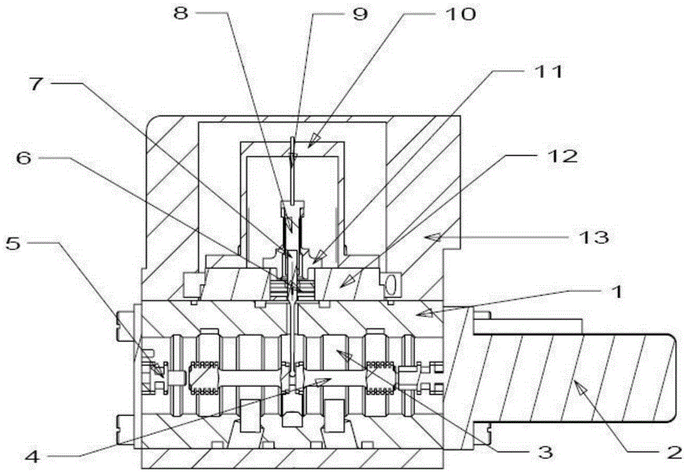
[0012] The structure of the present invention mainly includes structures such as a valve body, a valve sleeve, a valve core, a sensor, a piezoelectric chip, a spring tube, a reaction force rod, and a connecting rod. The first section of the piezoelectric bimorph is assembled in the middle of the support structure by means of press-fit connection, the end is connected with the connecting rod by press-fit, the connecting rod is respectively connected with the spring tube and the reaction rod through press-fit, and the support structure and the spring tube are installed by screws On the upper shell, the jet component is installed inside the upper shell, which forms a jet structure together with the narrow groove in the reaction rod; the sensor is connected to the end surface of the valve body, the valve sleeve and the valve core are installed inside the valve body, and t...


PUM


Abstract

The invention relates to a deflecting plate jet flow electro-hydraulic servo valve based on a piezoelectric structure. The valve comprises a valve body 1, a sensor 2, a valve pocket 3, a valve element 4, an end cap 5, a jet flow assembly 6, a counter-force rod 7, a connecting rod 8, a piezoelectric bimorph 9, a support structure 10, a bourdon tube 11, an upper shell 12 and an outer cover 13 and is characterized in that the head end of the piezoelectric bimorph 9 is assembled in the middle of the support structure 10 through a press fit connection manner, and the tail end of the piezoelectric bimorph 9 is connected with the connecting rod 8 through a press fit connection manner; the connecting rod 8 is connected with the bourdon tube 11 and the counter-force rod 7 through a press fit manner; the support structure 10 and the bourdon tube 11 are mounted on the upper shell 12 through screws; the jet flow assembly 6 is mounted in the upper shell 12; the jet flow assembly 6 and a narrow groove in the counter-force rod 7 form a jet flow structure; the end face of the valve body 1 is connected with the sensor 2; the valve pocket 3 and the valve element 4 are mounted in the valve body 1; the upper shell 12 is mounted on the valve body 1 through threaded connection; and the counter-force rod 7 goes deep into the valve body 1 through a circular hole and is connected with the valve element 4.

Description

technical field [0001] The invention belongs to the electro-hydraulic servo valve technology, in particular to a deflection plate jet electro-hydraulic servo valve based on piezoelectric structure. Background technique [0002] The deflector jet servo valve is a new jet electro-hydraulic servo valve, which is used to replace the traditional nozzle-baffle electro-hydraulic servo valve. Compared with the nozzle-baffle electro-hydraulic servo valve, the deflector jet servo valve has With the characteristics of high pollution resistance and high reliability, it can replace the nozzle-baffle electro-hydraulic servo valve in many fields such as aviation, aerospace, heavy machinery, and equipment manufacturing. A typical deflector jet servo valve adopts a torque motor structure to drive the rotation of the armature assembly, and produces a relative displacement between the deflector plate and the jet disc, which in turn causes the output pressure difference of the pre-stage, thereb...

Claims


Application Information

Patent Timeline
Patent Type & Authority Applications(China)
IPC IPC(8): F15B13/02
Inventor 刘志会王少华齐广峰
Owner FLIGHT AUTOMATIC CONTROL RES INST
Learn More