Buffering hydraulic cylinder

A buffering hydraulic cylinder and buffering spring technology, applied in the field of buffering hydraulic cylinders, can solve the problems of deformation of the hydraulic cylinder wall and piston, affecting the service life, deforming the cylinder body, etc., to reduce non-axial force, improve heat dissipation efficiency, avoid effect of stress

Active Publication Date: 2017-05-17
TIANJIN SHUANGXIANG ENG HYDRAULICS
View PDF6 Cites 8 Cited by
  • Summary
  • Abstract
  • Description
  • Claims
  • Application Information

AI Technical Summary

Problems solved by technology

When the hydraulic cylinder is used for a long time, the high-frequency friction of the piston will generate a lot of heat during the working process, which is prone to deformation and cylinder damage; especially for hydraulic cylinders used in high-temperature environments, the environment itself has a very high temperature. Coupled with the heat generated by high-speed friction and the impact between the piston and the cylinder, it is easy to cause local deformation of the hydraulic cylinder wall and piston, which affects the service life

Method used


Image

  • Buffering hydraulic cylinder
  • Buffering hydraulic cylinder
  • Buffering hydraulic cylinder

Examples


Embodiment 1

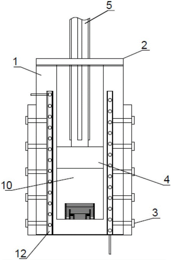
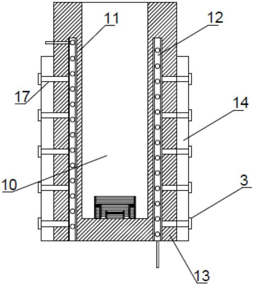
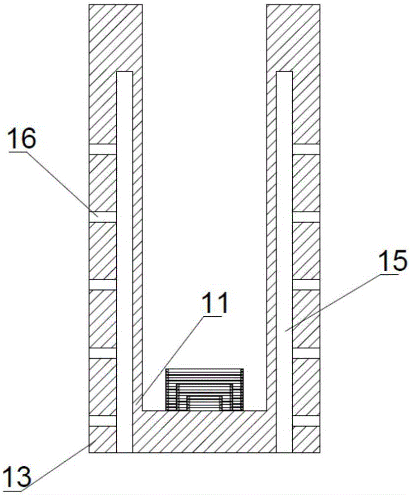
[0019] Such as Figure 1-6 As described above, this embodiment provides a buffer hydraulic cylinder, including a cylinder body 1, a cylinder head 2, a hollow bolt tube 3, a piston 4, and a piston rod 5; the bottom of the piston rod 5 is connected to the piston 4; the cylinder body 1 is a metal cylindrical structure, one end of which is provided with a cylinder head 2; the cylinder body 1 is sequentially composed of a cavity 10, a cylinder inner wall 11, a water cooling device 12, a cylinder outer wall 13 and a heat dissipation device 14 from the inside to the outside; the water cooling device 12 Installed in the annular slot 15 between the cylinder inner wall 11 and the cylinder outer wall 13; the water cooling device 12 is a cylindrical structure, including an inner cylinder 21, an outer cylinder 22 and a spiral water cooling tube 23; the spiral water cooling tube 23 Installed between the inner cylinder 21 and the outer cylinder 22; the two ends of the spiral water cooling pi...

Embodiment 2

[0021] Such as Figure 1-6 As shown, this embodiment provides a buffer hydraulic cylinder, different from Embodiment 1, the side wall of the piston rod 5 is provided with an outwardly protruding positioning bar; the top of the cylinder head 2 is provided with a plurality of annular heat sink.

Embodiment 3

[0023] Such as Figure 1-6 As shown, this embodiment provides a buffer hydraulic cylinder, different from Embodiment 2, the buffer device includes three buffer springs, the first buffer spring 31 with the largest diameter, the second buffer spring 32 and the first buffer spring with the smallest diameter Three buffer springs 33; the first buffer spring 31, the second buffer spring 32 and the third buffer spring 33 are concentrically arranged, and the diameter and height gradually decrease from the outside to the inside; the first buffer spring 31, the second buffer spring 32 and the third buffer spring The height ratio of the buffer spring 33 is 3:2:1.


PUM


Abstract

The invention provides a buffering hydraulic cylinder. A cylinder body is sequentially composed of a cavity body, a cylinder body inner wall, a water-cooling device, a cylinder body outer wall and a heat dissipation device from inside to the outside. The water-cooling device is installed in an annular inserting groove between the cylinder body inner wall and the cylinder body outer wall and of a cylinder-shaped structure, and the water-cooling device comprises an inner cylinder body, an outer cylinder body and a spiral water-cooling pipe; and the spiral water-cooling pipe is installed between the inner cylinder body and the outer cylinder body, and a water inlet and a water outlet are formed in the two ends of the spiral water-cooling pipe correspondingly. A plurality of threaded through holes are formed in the cylinder body outer wall. The heat dissipation device is of a cooper cylinder-shaped structure and nested in the cylinder body outer wall, a plurality sets of dissipation fins are installed on the outer surface of the heat dissipation device, and a plurality sets of through holes are formed in the side wall of the heat dissipation device. Hollow bolt pipes are each a hollow copper bolt, a sealed structure with an outer thread is installed at the bottom of each hollow bolt pipe, the hollow bolt pipes penetrate through the heat dissipation device and are fixed to the threaded holes of the cylinder body outer wall. A buffering device comprises a plurality of buffering springs which are concentrically installed at the bottom of the cavity body, and the diameters of the buffering springs are different.

Description

technical field [0001] The invention relates to the technical field of hydraulic components, in particular to a buffer hydraulic cylinder. Background technique [0002] A hydraulic cylinder is a hydraulic actuator that converts hydraulic energy into mechanical energy and performs linear reciprocating motion. It has simple structure and reliable operation. When it is used to realize reciprocating motion, the deceleration device can be eliminated, and there is no transmission gap, and the motion is stable, so it is widely used in various mechanical hydraulic systems. When the hydraulic cylinder is used for a long time, the high-frequency friction of the piston will generate a lot of heat during the working process, which is prone to deformation and cylinder damage; especially for hydraulic cylinders used in high-temperature environments, the environment itself has a very high temperature. Coupled with the heat generated by high-speed friction and the impact between the pisto...

Claims


Application Information

Patent Timeline
Patent Type & Authority Applications(China)
IPC IPC(8): F15B15/14F15B15/22F15B21/04
CPCF15B15/1423F15B15/1428F15B15/1438F15B15/1457F15B15/22F15B21/042
Inventor 吕技选
Owner TIANJIN SHUANGXIANG ENG HYDRAULICS
Why Eureka
Try Eureka