Signal generating system for aging tests

A technology for signal generation and testing, applied in the direction of electronic circuit testing, measuring devices, instruments, etc., can solve problems such as failure to meet aging test conditions, functional limitations of aging boxes, etc., to reduce the inconvenience of converting data, reduce workload, and improve The effect of work efficiency

Active Publication Date: 2017-05-17
BEIJING MXTRONICS CORP +1
View PDF6 Cites 5 Cited by
  • Summary
  • Abstract
  • Description
  • Claims
  • Application Information

AI Technical Summary

Problems solved by technology

[0003] The technical problem solved by the present invention is: compared with the prior art, it provides a signal generating system for burn-in test, which solves the problem that the existing burn-in test conditions cannot be satisfied due to the functional limitation of the burn-in box

Method used


Image

  • Signal generating system for aging tests
  • Signal generating system for aging tests
  • Signal generating system for aging tests

Examples


Embodiment Construction

[0018] Below in conjunction with accompanying drawing, the present invention is described in further detail:

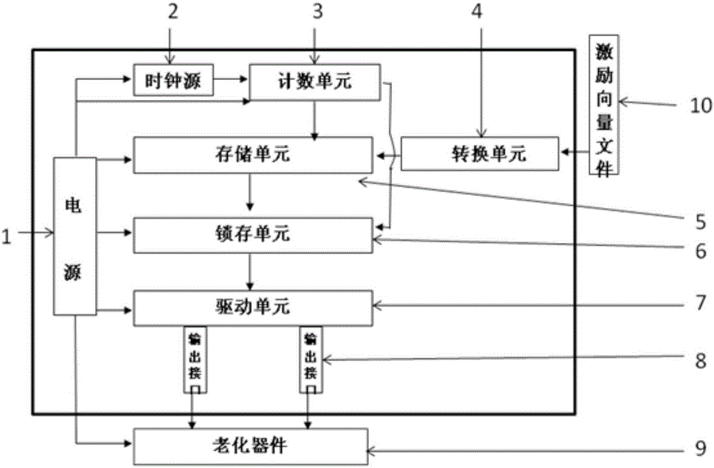
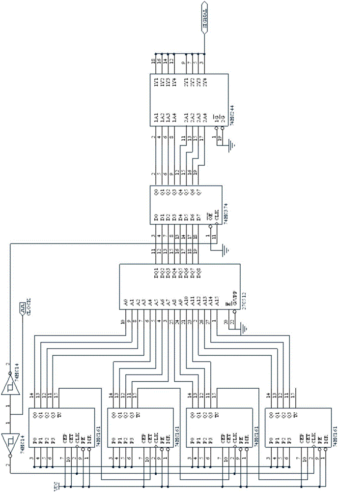
[0019] figure 1 A schematic structural diagram of a signal generation system for a burn-in test provided by an embodiment of the present invention is shown. Such as figure 1 As shown, the signal generating system for the burn-in test includes: a power supply 1 , a clock source 2 , a counting unit 3 , a conversion unit 4 , a storage unit 5 , a latch unit 6 , a drive unit 7 and an output interface 8 . in,

[0020] The power supply 1 is respectively connected to the clock source 2, the counting unit 3, the storage unit 5, the latch unit 6, the drive unit 7 and the aging device 9, and the power supply 1 is respectively supplied to the clock source 2, the counting unit 3, the storage unit 5, and the latch unit 6. The driving unit 7 and the burn-in device 9 provide voltage. Specifically, one end of the power supply 1 provides a voltage of +5V for the clock source 2 , th...


PUM


Abstract

The invention discloses a signal generating system for aging tests. The signal generating system comprises a power source, a clock source, a counting unit, a conversion unit, a storage unit, a latch unit, a driving unit and an output interface. The clock source is used for outputting square-wave clock pulse signals; the counting unit is used for receiving the square-wave clock pulse signals and can be triggered by rising edges of square-wave clock signal pulses to output counting states, so that address data signals can be outputted by the counting unit; the storage unit is used for receiving and storing the address data signals; excitation vector files can be converted into excitation vector files in required formats by the conversion unit; required excitation signal waveforms can be outputted by the storage unit; second excitation signal waveforms which change along with the excitation signal waveforms can be outputted by the latch unit; the driving unit is used for receiving the second excitation signal waveforms and providing the second excitation signal waveforms to aging devices. The signal generating system has the advantage that the problem of incapability of meeting conditions of existing aging tests due to functional limitation of aging ovens can be solved.

Description

technical field [0001] The invention relates to the field of integrated circuit screening, in particular to a signal generating system for burn-in tests. Background technique [0002] During the reliability test of military integrated circuits, devices with reliability levels must undergo aging screening under specified conditions at specified time and temperature according to different levels of requirements. During the test, all circuits need to apply appropriate excitation signals to simulate as much as possible In practical applications, the dynamic aging method is used to simulate the application state. The most complicated way in dynamic aging is to simulate the waveform diagram of the functional test, and apply the excitation signal according to the vector file provided by the designer to simulate the actual application as much as possible. Due to the technical difficulty of this method, most of the peers can only realize it through aging boxes at home and abroad. H...

Claims


Application Information

Patent Timeline
Patent Type & Authority Applications(China)
IPC IPC(8): G01R31/28G01R1/28
CPCG01R1/28G01R31/2855
Inventor 王茉张立康智淼胡会献
Owner BEIJING MXTRONICS CORP
Why Eureka
Try Eureka