Zero-transition low-voltage intelligent reactive power compensation control device

A compensation control and intelligent technology, applied in the direction of reactive power compensation, reactive power adjustment/elimination/compensation, etc., can solve problems such as inapplicability, and achieve the effect of strong applicability, good practicability, and rich and intuitive display content

Pending Publication Date: 2017-05-17
恒一电气集团有限公司
View PDF0 Cites 3 Cited by
  • Summary
  • Abstract
  • Description
  • Claims
  • Application Information

AI Technical Summary

Problems solved by technology

Therefore, none of the above solutions can be applied to sites with large load changes and frequent changes.

Method used


Image

  • Zero-transition low-voltage intelligent reactive power compensation control device

Examples


Embodiment 1

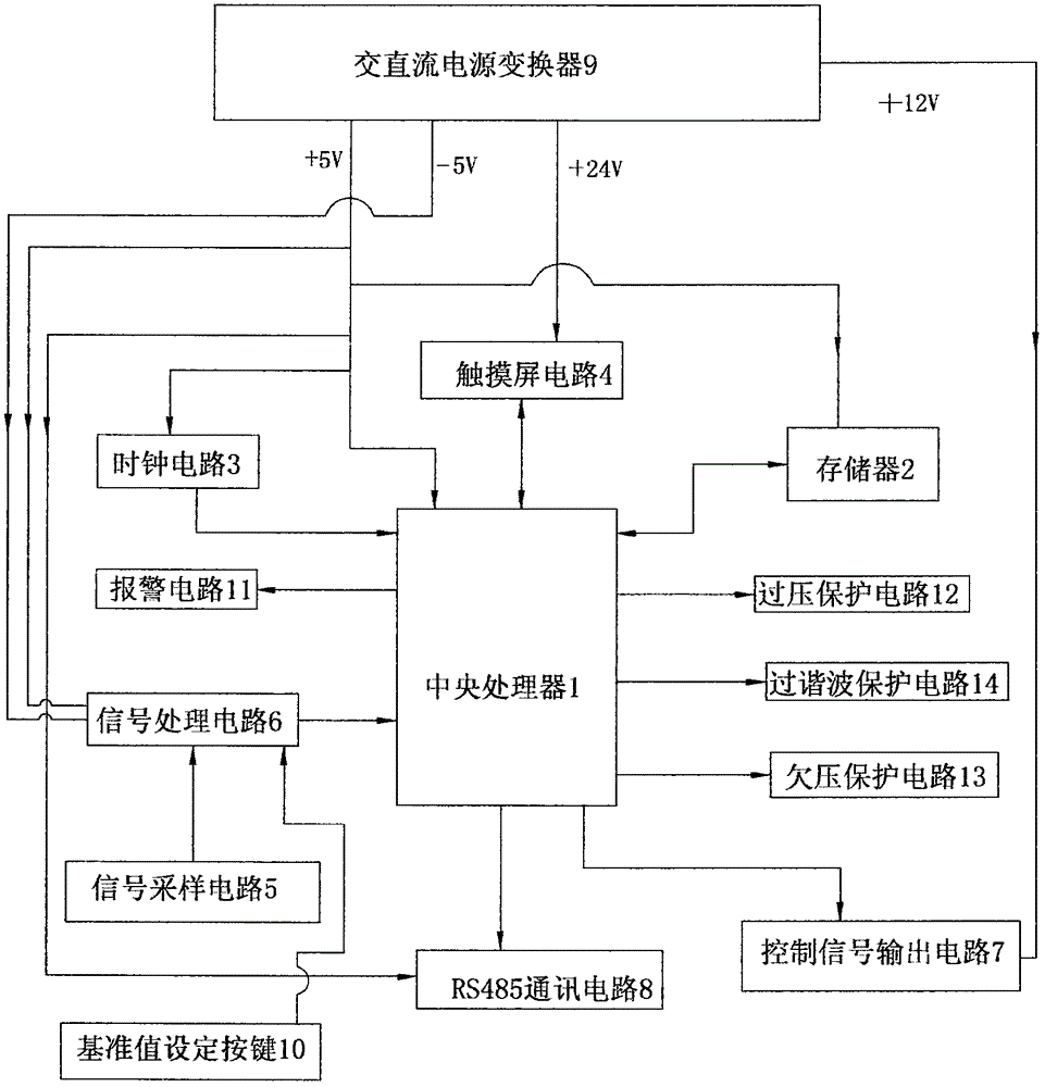
[0025] figure 1 A specific embodiment of the invention is shown in which figure 1 It is a structural schematic diagram of the present invention.

[0026] See figure 1 , a zero-transition low-voltage intelligent reactive power compensation control device, including

[0027] The central processing unit 1 is used for full-wave sampling of the voltage and current of each phase, calculating the amplitude and harmonic content, comparing the zero-crossing of the voltage and current of each phase, and converting the phase angle into an asynchronous time;

[0028] The memory 2 is connected with the central processing unit through a cable, and is used to store the maximum and minimum values ​​of the voltage and current power factors and the historical data of power saving; the memory adopts a 2GB TF card for storing 12 months of historical data. The historical data includes the maximum and minimum values ​​of the voltage and current power factors every day, and the cumulative referen...


PUM


Abstract

The invention discloses a zero-transition low-voltage intelligent reactive power compensation control device which comprises a central processor, a storage device in connection with the central processor through a cable, a time clock circuit in connection with the central processor through a cable, a touch screen circuit in connection with the central processor through a cable, a signal sampling circuit used to synchronously sample the voltage signals and the current signals of various phases, a signal processing circuit connected between the signal sampling circuit and the central processor through a cable, a control signal output circuit in connection with the central processor through a cable, an RS485 communication circuit in connection with the central processor through a cable and an alternating current and direct current converter. The structure of the device is reasonably designed to realize the rapid reactive power compression without any delay so that over-compensation or lacked compensation could be avoided. Therefore, the shortcomings seen in the prior art related with delayed compensation or lacked compensation could be well addressed. In addition, the device is stable and practical in use.

Description

technical field [0001] The invention belongs to the technical field of low-voltage 0.4KV fast reactive power compensation equipment, and in particular relates to a zero-transition low-voltage intelligent reactive power compensation control device. Background technique [0002] Most of the electric loads in the power grid are inductive loads, such as motors and transformers. Corresponding reactive power needs to be provided to these devices during operation, resulting in a decrease in power factor, an increase in line current, and an increase in power loss. After installing reactive power compensation equipment such as shunt capacitors in the grid, it can provide reactive power consumed by inductive loads, reducing the reactive power provided by the grid power supply to the inductive load and transmitted by the line, due to the reduction of reactive power in the grid Therefore, it can reduce the power loss caused by the transmission of reactive power in lines and transformer...

Claims


Application Information

Patent Timeline
IPC IPC(8): H02J3/18
CPCH02J3/18Y02E40/30
Inventor 林锡洪李伟郑伟雷生华李文杰
Owner 恒一电气集团有限公司
Why Eureka
Try Eureka