
Storage battery circuit structure

A circuit structure, battery technology, applied in battery circuit devices, circuit devices, safety/protection circuits, etc., can solve problems such as complex structure, achieve the effect of simple circuit structure and improve service life

Inactive Publication Date: 2017-05-17
四川升能泰科技有限公司
View PDF5 Cites 0 Cited by
  • Summary
  • Abstract
  • Description
  • Claims
  • Application Information

AI Technical Summary

Problems solved by technology

However, the existing charging protection circuit has a complicated structure

Method used


Image

  • Storage battery circuit structure

Examples


Embodiment 1

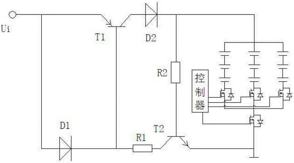
[0017] Such as figure 1 The shown battery circuit structure includes a battery pack and a charging circuit connected to the battery pack, the battery pack is connected with a charging protection circuit, and the charging circuit includes a first triode, a first diode and The second diode, the emitter of the first triode and the anode of the first diode are connected to the charging port, the cathode of the first diode is connected to the base of the first triode connected, the collector of the first triode is connected to the anode of the second diode and the cathode of the second diode is connected to the anode of the battery pack, and the charging protection circuit includes the second triode , the collector of the second diode is connected to the cathode of the first diode through the first resistor and the base is connected to the cathode of the second diode through the second resistor, and the emission of the second diode The pole is connected to the cathode of the batte...

Embodiment 2

[0019] Existing batteries generally use a battery pack composed of multiple batteries to meet the requirements of large capacity. It uses a plurality of batteries connected in parallel to form a battery pack that meets a certain capacity requirement, and then multiple battery packs are connected in series to form a large-capacity battery that meets a certain capacity and a certain rated voltage. However, there is a disadvantage of using this method, that is, if the parameters in a single battery pack do not match, such as internal resistance, when the battery stops working, since a single battery pack is composed of multiple batteries connected in parallel, a discharge circuit must be formed in the battery pack. After a period of time, the battery capacity will drop significantly, which will damage the service life of the battery. When the parameters of each battery in the battery pack do not match, the loss will be more obvious. In order to solve the above technical problems,...


PUM


Abstract

The invention discloses a storage battery circuit structure. The storage battery circuit structure comprises a battery pack and a charging circuit connected onto the battery pack and is characterized in that a charging protection circuit is connected onto the battery pack, wherein the charging protection circuit comprises a first triode, a first diode and a second diode, an emitter of the first triode and a positive electrode of the first diode are both connected onto a charging port, a negative electrode of the first diode is connected with a base of the first triode, a collector of the first triode is connected with a positive electrode of the second diode, a negative electrode of the second diode is connected with a positive electrode of the battery pack, the charging protection circuit comprises a second triode, a collector of the second triode is connected with the negative electrode of the first diode through a first resistor, a base of the second triode is connected with the negative electrode of the second diode through a second resistor, and an emitter of the second diode is connected with a negative electrode of the battery pack. The circuit structure has a charging protection function and is simple.

Description

technical field [0001] The invention relates to the battery field, in particular to a storage battery circuit structure. Background technique [0002] Batteries as energy storage elements are widely used. When the battery is being charged, its reverse connection is bound to cause damage to the battery. Most of the existing battery charging circuits contain charging protection circuits. However, the existing charging protection circuit has a complex structure. Contents of the invention [0003] In order to solve the above technical problems, the present invention provides a storage battery circuit structure, which has a charging protection function and has a simple circuit structure. [0004] The present invention realizes through following technical scheme: [0005] A storage battery circuit structure, comprising a battery pack and a charging circuit connected to the battery pack, characterized in that a charging protection circuit is connected to the battery pack, and...

Claims


Application Information

Patent Timeline
Patent Type & Authority Applications(China)
IPC IPC(8): H02J7/00
CPCH02J7/0013H02J7/0034
Inventor 钟东龙
Owner 四川升能泰科技有限公司
Learn More