Multi-mode control method and device

A control method and multi-mode technology, which can be used in control/regulation systems, output power conversion devices, and adjustment of electrical variables, etc., and can solve excessive core losses and conduction losses, large switching losses, and large filtering pressure problems, to achieve the effect of improving adaptability and optimizing performance

Active Publication Date: 2017-05-17
SUNGROW POWER SUPPLY CO LTD
View PDF7 Cites 13 Cited by
  • Summary
  • Abstract
  • Description
  • Claims
  • Application Information

AI Technical Summary

Problems solved by technology

This working mode is very simple, but it is based on the fact that the inductor L1 first stores energy and then releases energy in each switching cycle. The ripple current of the inductor is very large, resulting in excessive core loss and conduction loss. , and the filtering pressure is also greater
In ad...

Method used


Image

  • Multi-mode control method and device
  • Multi-mode control method and device
  • Multi-mode control method and device

Examples


Embodiment Construction

[0050]The following will clearly and completely describe the technical solutions in the embodiments of the present invention with reference to the accompanying drawings in the embodiments of the present invention. Obviously, the described embodiments are only some, not all, embodiments of the present invention. Based on the embodiments of the present invention, all other embodiments obtained by persons of ordinary skill in the art without making creative efforts belong to the protection scope of the present invention.

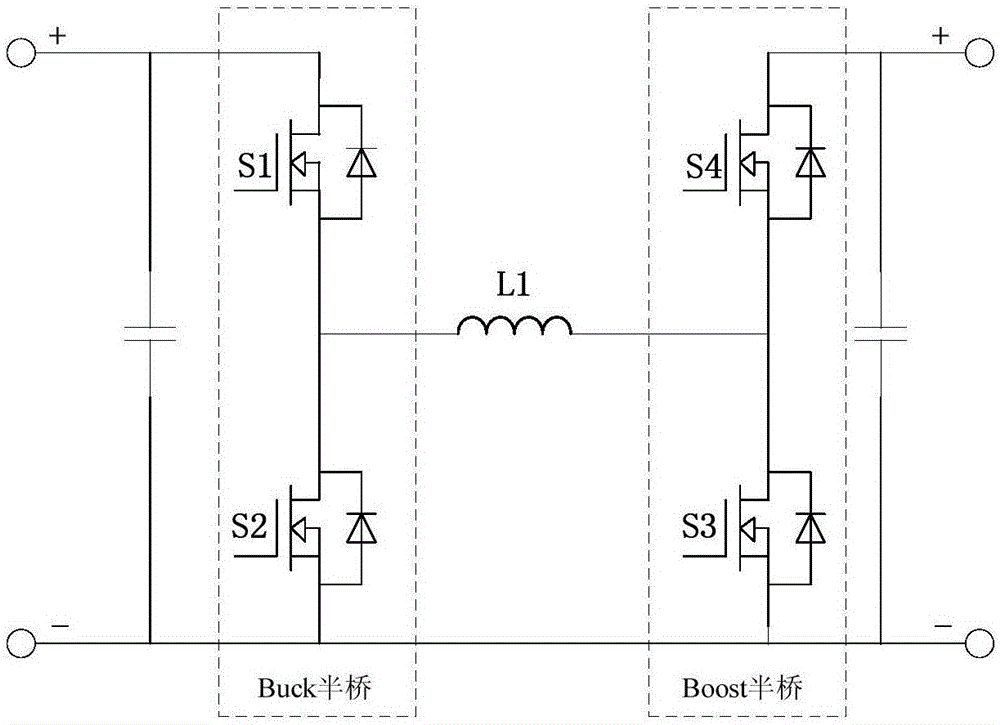
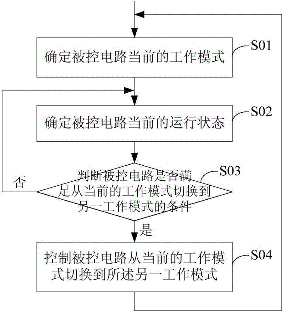
[0051] see figure 1 , the embodiment of the present invention discloses a multi-mode control method to improve the adaptability of power electronic circuits to complex applications, including:

[0052] Step S01: Determine the current working mode of the controlled circuit (that is, the power electronic circuit as the research object); wherein, a variety of working modes are set for the controlled circuit in advance, and the operating areas of different working ...


PUM


Abstract

The application discloses a multi-mode control method and device. The multi-mode control method comprises the following steps of: determining the current working mode of a controlled circuit; presetting multiple working modes for the controlled circuit, dividing operation areas in different working modes by adopting performance optimization of the controlled circuit as an objective, and determining the condition for switching among the different working modes according to boundary values of all the operation areas; determining the current operation state of the controlled circuit; judging whether the controlled circuit meets the condition for switching from the current working mode to another working mode according to the current operation state of the controlled circuit; and if so, controlling the controlled circuit to switch from the current working mode to another working mode so as to improve the adaptability of power electronic circuits to complex application occasions.

Description

technical field [0001] The present invention relates to the technical field of power electronics, and more specifically, to a multi-mode control method and device. Background technique [0002] With the complexity of the application of power electronics technology, the traditional working mode of some power electronics circuits can no longer meet the current work requirements. [0003] For example, the topology of a full-bridge Buck-Boost circuit is as follows figure 1 As shown, it can be regarded as the cascade connection of the Buck half bridge and the Boost half bridge. Specifically: S1 and S2 are the upper and lower tubes of the Buck half bridge, S4 and S3 are the upper and lower tubes of the Boost half bridge, and L1 is the common inductance of the two bridge halves. The full-bridge Buck-Boost circuit usually works in the mode where the upper and lower transistors of the same half bridge are turned on alternately, and the upper and lower transistors of different half ...

Claims


Application Information

Patent Timeline
IPC IPC(8): H02M1/00H02M1/088H02M3/145
CPCH02M1/00H02M1/088H02M3/145H02M1/0006H02M1/0048Y02B70/10
Inventor 谷雨谢晶晶徐君
Owner SUNGROW POWER SUPPLY CO LTD
Why Eureka
Try Eureka