LTE (Long Term Evolution) base station system, cell merging method and cell splitting method

A base station system and community technology, applied in the field of communication, can solve the problems of large coverage area, poor experience, and high penetration loss of macro base stations, and achieve the effects of low technical complexity, high noise floor, and easy deployment

Active Publication Date: 2017-05-17
BOOMSENSE TECH
View PDF6 Cites 8 Cited by
  • Summary
  • Abstract
  • Description
  • Claims
  • Application Information

AI Technical Summary

Problems solved by technology

[0002] At present, according to the theory of electromagnetic propagation, the higher the frequency band, the worse the signal propagation ability and the higher the penetration loss, and the 4GLTE (fourth generation cellular communication system) signal is usually located in the high frequency band (for example, the frequency range of Band38 is 2570MHz-2620MHz) , so that the 4G signal of the outdoor macro base station has weak indoor coverage, and indoor coverage blind spots are prone to appear.
On the other hand, most of the 4G services take place indoors, and the macro base station has a large coverage area, and its wireless resources are shared by a large number of users, so the experience for a single user is poor, especially in densely populated hotspot areas
[0003] Deploying small base stations indoors can enhance indoor coverage and improve user experience in hotspot areas, but small base stations face the following problems when deployed indoors: 1) Limited coverage
The indoor environment is compl

Method used


Image

  • LTE (Long Term Evolution) base station system, cell merging method and cell splitting method
  • LTE (Long Term Evolution) base station system, cell merging method and cell splitting method
  • LTE (Long Term Evolution) base station system, cell merging method and cell splitting method

Examples


Embodiment Construction

[0022] The specific implementation manners of the present invention will be further described in detail below in conjunction with the accompanying drawings and embodiments. The following examples are used to illustrate the present invention, but are not intended to limit the scope of the present invention.

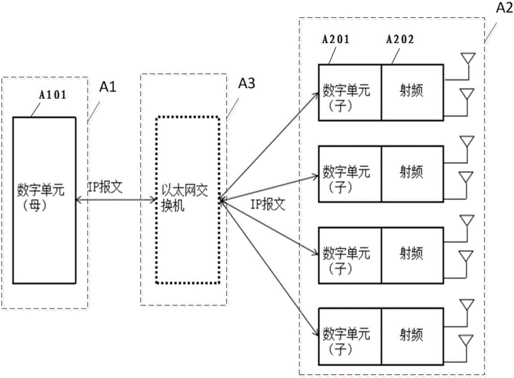
[0023] Such as image 3 , in a specific implementation of the present invention, a schematic diagram of an overall architecture of an LTE base station system is shown. Generally speaking, it includes a near-end module A1, a far-end module A2 and an Ethernet switching module A3: the near-end module A1 is composed of a digital unit A101 split from the LTE base station digital unit, and is used to be responsible for LTE layer 2 (i.e. LTE layer two, abbreviated as LTE L2, including MAC, RLC, PDCP sub-layers) and the processing of the upper layer; the remote module has several, which are split from the digital subunit A201 and The radio frequency unit A202 is formed, and the ...


PUM


Abstract

The present invention provides an LTE (Long Term Evolution) base station system, a cell merging method and a cell splitting method. According to the LTE (Long Term Evolution) base station system, the cell merging method and the cell splitting method, an LTE base station digital unit is split into a digital parent unit and digital child units; the digital parent unit is responsible for the processing of an LTE layer 2 and layers above the LTE layer 2; the digital child units are responsible for the processing of an LTE layer 1; and the digital child units and radio frequency modules constitute remote-end modules of the LTE (Long Term Evolution) base station system of the present invention; the digital parent unit constitutes the near-end module of the LTE (Long Term Evolution) base station system of the present invention; the near-end module communicates with the emote end modules through a standard IP network, and therefore, deployment and expansion can be facilitated; related devices, modules or algorithms for optical communication, signal conversion, signal compression/decompression and so on are not required to be adopted, and therefore, technical complexity is low, and costs are low; and the remote-end modules independently perform demodulation and decoding, and therefore, the problem of ground noise rise caused by signal merging in the prior art can be solved.

Description

technical field [0001] The present invention relates to the technical field of communication, and more specifically, relates to an LTE base station system and a cell merging and splitting method. Background technique [0002] At present, according to the theory of electromagnetic propagation, the higher the frequency band, the worse the signal propagation ability and the higher the penetration loss, and the 4GLTE (fourth generation cellular communication system) signal is usually located in the high frequency band (for example, the frequency range of Band38 is 2570MHz-2620MHz) , so that the 4G signal of the outdoor macro base station has weak indoor coverage, and indoor coverage blind spots are prone to appear. On the other hand, most of the 4G services take place indoors, and the macro base station covers a large area, and its wireless resources are shared by a large number of users, which makes the user experience poor, especially in densely populated hotspot areas. [00...

Claims


Application Information

Patent Timeline
IPC IPC(8): H04W88/08H04W16/02
CPCH04W16/02H04W88/085
Inventor 王金灵王聪
Owner BOOMSENSE TECH
Why Eureka
Try Eureka