
Integral type eccentric back spotfacing tool

A kind of integral, cutting tool technology, applied in the direction of cutting tools used in lathes, manufacturing tools, tool holder accessories, etc., can solve the problem that countersinking can not meet the needs of production and quality requirements, and the efficiency of countersinking is low in countersinking , Complicated operation of mechanics and other problems, to achieve the effect of simple structure, high processing quality and convenient operation

Inactive Publication Date: 2017-05-24
NINGXIA KOCEL MOLD
View PDF6 Cites 2 Cited by
  • Summary
  • Abstract
  • Description
  • Claims
  • Application Information

AI Technical Summary

Problems solved by technology

[0002] With the continuous improvement of gas turbine engine design performance, gas turbine engine parts are updated quickly, with many varieties and high requirements. This development trend will definitely drive the progress of gas turbine parts processing technology and cutting tool technology. It consists of a cutter body, a detachable cutter head and a blade. The blade is installed on the detachable cutter head. This type of countersinking tool is inefficient in machining countersunk holes, and the machinist’s operation is complicated and the quality risk is high.
The number of bolt holes on the joint surface of different types of gas turbine parts varies, and the number of bolt holes on the joint surface of large and medium-sized parts exceeds 50. For this type of parts, the traditional countersinking tool cannot meet the needs of production and quality requirements

Method used


Image

  • Integral type eccentric back spotfacing tool
  • Integral type eccentric back spotfacing tool
  • Integral type eccentric back spotfacing tool

Examples


Embodiment Construction

[0016] In order to enable those skilled in the art to better understand the technical solutions of the present invention, the present invention will be further described in detail below in conjunction with specific examples. The embodiments described below are exemplary and are only used for explaining the present invention, and should not be construed as limiting the invention. If no specific technique or condition is indicated in the examples, it shall be carried out according to the technique or condition described in the literature in this field or according to the product specification.

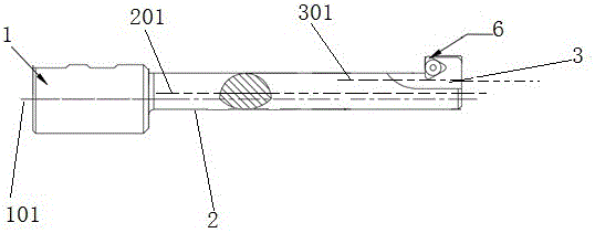
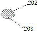
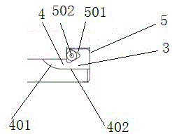
[0017] The present invention provides an integral eccentric countersinking tool, according to an embodiment of the present invention, figure 1 It is the structural representation of the integral type eccentric countersinking tool of the present invention, with reference to figure 1 As shown, the cutter of the present invention includes: a tool seat 1, a tool bar 2 and a cutter head 3, w...


PUM


Abstract

The invention relates to the field of gas turbine part machining and particularly relates to an integral type eccentric back spotfacing tool. The integral type eccentric back spotfacing tool comprises a tool apron, a tool bar and a tool bit, wherein the tool bar adopts an asymmetric structure; the tool bit comprises an arc-shaped groove and a connecting block, and the tool bit is divided into a front side and a rear side in an axial direction from a vertical direction; the arc-shaped groove is located at the front side of the tool bit, the arc-shaped groove is formed by that a part of arc body is sheared from the middle of the tool bit in the axial direction, and the arc-shaped groove is formed by connecting a concave cambered surface and a horizontal surface from top to bottom; the cambered surface is close to one side of the tool bar, and both the cambered surface and the horizontal surface are located above the central axis of the tool bar; the connecting block is located on the back side of the tool bit in the vertical direction; and the central axis of the tool apron is not coincided with the central axis of the tool bar, and the central axis of the tool bit is located above the central axis of the tool apron. The integral type eccentric back spotfacing tool has the advantages that the structure is simple, and the operation is convenient; and when massive complicated back spotfacing is carried out, the machining quality is high, and the efficiency is high.

Description

technical field [0001] The invention relates to the field of mechanical processing of gas turbine parts, and is especially suitable for counterbore machining of upper and lower half combined cylinder parts combined cylinder holes, and in particular relates to an integral eccentric countersinking tool. Background technique [0002] With the continuous improvement of gas turbine engine design performance, gas turbine engine parts are updated quickly, with many varieties and high requirements. This development trend will definitely drive the progress of gas turbine parts processing technology and cutting tool technology. It consists of a cutter body, a detachable cutter head and a blade. The blade is installed on the detachable cutter head. This type of countersinking tool is inefficient in machining countersunk holes, and the machinist’s operation is complicated and the quality risk is high. The number of bolt holes on the joint surface of different types of gas turbine parts ...

Claims


Application Information

Patent Timeline
IPC IPC(8): B23B27/00B23B29/02
CPCB23B27/00B23B29/02
Inventor 岳岁宁
Owner NINGXIA KOCEL MOLD
Features
  • Generate Ideas
  • Intellectual Property
  • Life Sciences
  • Materials
  • Tech Scout
  • Unparalleled Data Quality
  • Higher Quality Content
  • 60% Fewer Hallucinations
Learn More