Material storing and material taking integrated automatic screw driving machine

A locking screw machine, an integrated technology, applied in metal processing, metal processing equipment, manufacturing tools and other directions, can solve the problems of single product, low production efficiency of locking screws, and occupation of locking time.

Active Publication Date: 2017-05-24
SHENZHEN MIGHT TECH
View PDF10 Cites 7 Cited by
  • Summary
  • Abstract
  • Description
  • Claims
  • Application Information

AI Technical Summary

Problems solved by technology

The existing structure of the screw machine has the following problems: due to the simple two-axis working mode, the products that can be locked are single and the degree of automation is low
Although the simple three-axis screw machine is compatible with a variety of products, the locking mechanism needs to reciprocate to the feeding mechanism to pick up materials during the material picking process, which takes up locking time and leads to low production efficiency of locking screws

Method used


Image

  • Material storing and material taking integrated automatic screw driving machine
  • Material storing and material taking integrated automatic screw driving machine
  • Material storing and material taking integrated automatic screw driving machine

Examples


Embodiment Construction

[0034] In order to make the technical problems, technical solutions and beneficial effects to be solved by the present invention clearer and more comprehensible, the present invention will be further described in detail below with reference to the accompanying drawings and embodiments. It should be understood that the specific embodiments described herein are only used to explain the present invention, but not to limit the present invention.

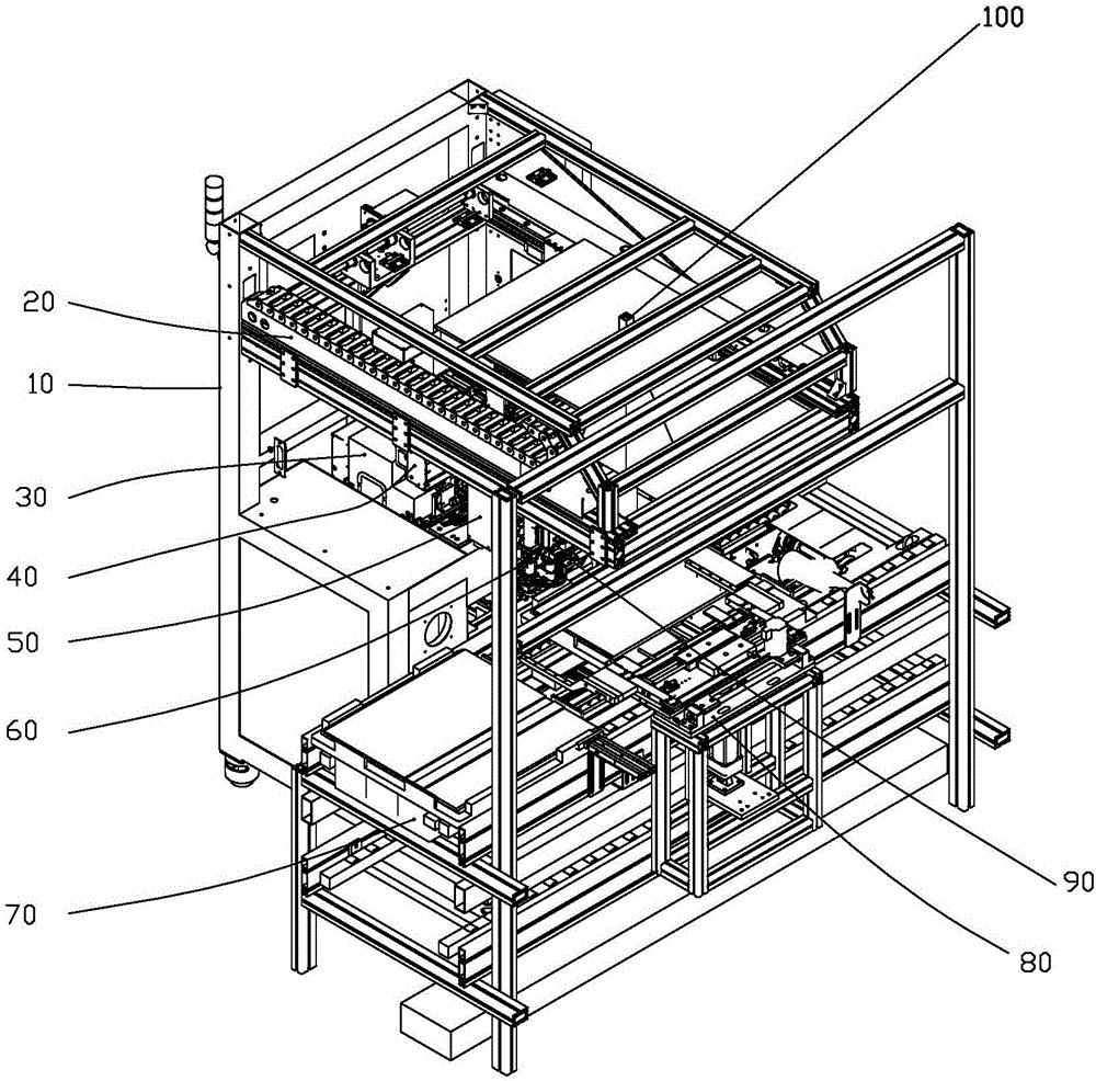
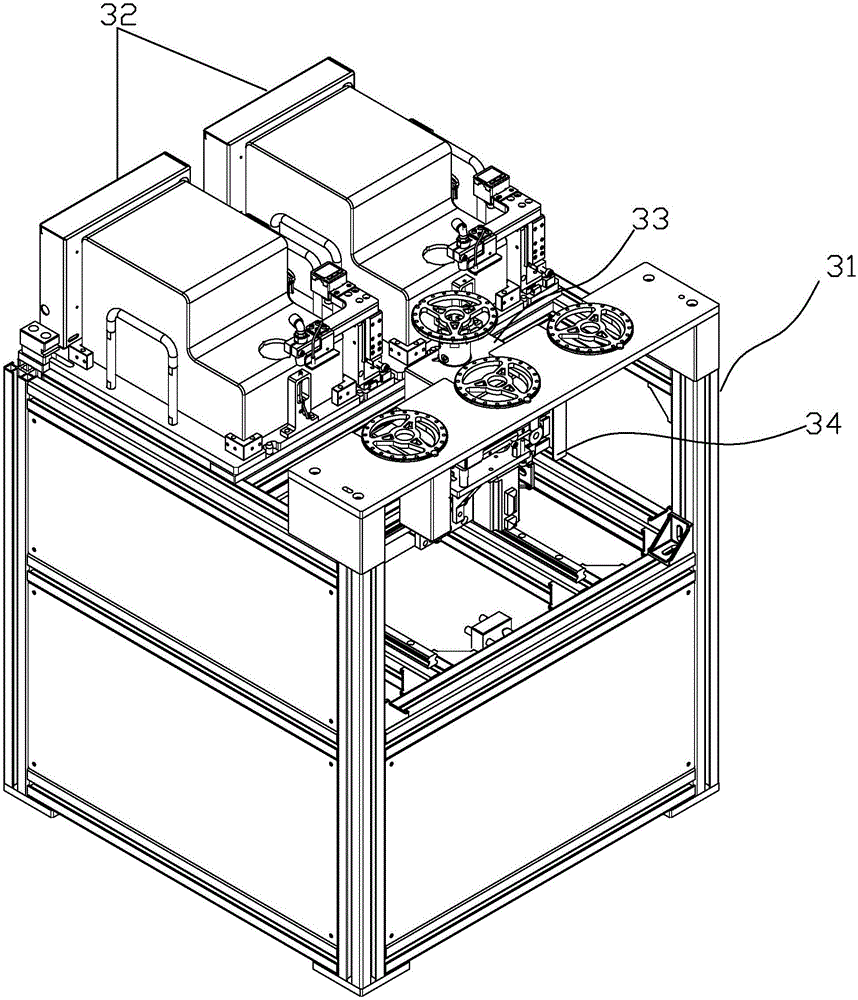
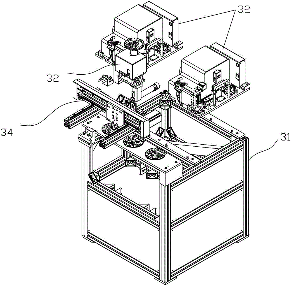
[0035] Please refer to Figure 1 to Figure 18 As shown, an integrated automatic locking screw machine for accessing materials is described below in conjunction with the embodiments, including a cabinet main body bracket 10, a cabinet attachment bracket installed on the side of the cabinet main body bracket 10; a Y-axis assembly 20, an X-axis assembly 40, and a Z-axis assembly 50. Feeding tray screw feeding system 30, left and right lifting and rotating locking device 60, CCD auxiliary positioning system 100, flipping fixture 80, product ...


PUM


Abstract

The invention relates to a material storing and material taking integrated automatic screw driving machine which comprises a cabinet main body bracket, a Y-axis assembly, an X-axis assembly and a Z-axis assembly as well as workpiece tray screw supply systems, a left and right lifting rotary locking device, a CCD auxiliary assistant positioning system, a front end clamp, an overturning clamp and a product line body mechanism; the Z-axis assembly is mounted on the X-axis assembly, the X-axis assembly is mounted on the Y-axis assembly, the Y-axis assembly is mounted on the cabinet main body bracket, the workpiece tray screw supply systems are mounted in the cabinet main body, the left and right lifting rotary locking device is mounted on the Z-axis assembly, the CCD auxiliary assistant positioning system is mounted on the top of the cabinet main body, and the front end clamp is mounted at the front end of the cabinet main body bracket to form the automatic screw driving machine. By adopting the plurality of workpiece tray screw supply systems, two electric screwdrivers are matched to realize locking for at least twenty times to reduce the reciprocative material-taking time and material-taking stroke, so that a purpose of improving the locking efficiency is achieved. The product locking stability and production efficiency are extremely improved.

Description

[0001] 【Technical field】 [0002] The invention relates to an integrated automatic locking screw machine for accessing materials used for assembling locking screws of electronic products. [0003] 【Background technique】 [0004] Locking screw fixing is a processing procedure in some electronic products. According to the complexity of different locking products, the existing screw machines are usually completed by X, Z two-axis gantry type and X, Y, Z three-axis mechanical arm motion mechanism. Move the positioning action to drive the electric batch or the wind batch locking mechanism to complete the screw attachment. The feeding mechanism in the screw machine uses the vibrating plate to discharge the material or supplemented by linear vibration to transmit the screw to the nozzle position, waiting for the electric batch to take the material. In addition, there is a product positioning mechanism on the main cabinet. The screw machine with the existing structure has the followi...

Claims


Application Information

Patent Timeline
Patent Type & Authority Applications(China)
IPC IPC(8): B23P19/06B23P19/00
CPCB23P19/001B23P19/06
Inventor 王大利
Owner SHENZHEN MIGHT TECH
Why Eureka
Try Eureka