Oil-gas lubrication structure of high-speed electric main shaft

A high-speed electric spindle and oil-air lubrication technology, which is applied to metal processing machinery parts, maintenance and safety accessories, metal processing equipment, etc., can solve problems such as strong frictional heat, burns, and failure to work normally

Inactive Publication Date: 2017-05-24
SHENZHEN SUFENG TECH +2
View PDF6 Cites 7 Cited by
  • Summary
  • Abstract
  • Description
  • Claims
  • Application Information

AI Technical Summary

Problems solved by technology

When the bearing is running at high speed, there will be complex friction between the bearing rollers and the inner and outer rings o...

Method used


Image

  • Oil-gas lubrication structure of high-speed electric main shaft

Examples


Embodiment

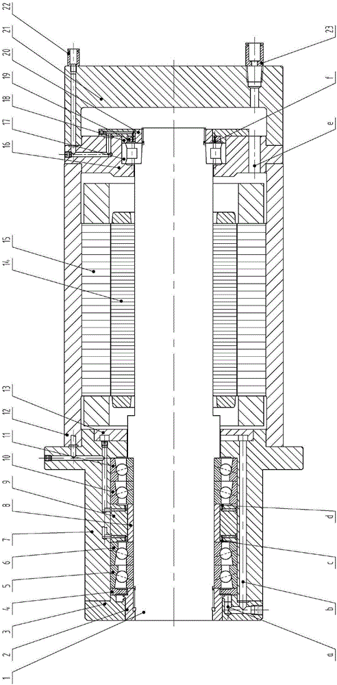
[0022] refer to figure 1 , the present invention relates to an oil-air lubrication structure for a high-speed electric spindle, which includes a spindle rotor 1, a front lock nut 2, a front gland 3, an adjustment ring 4, an angular contact ball bearing 5, an angular contact ball bearing 6, and a front bearing sleeve Barrel 7, inner spacer ring 8, outer spacer ring 9, angular contact ball bearing 10, angular contact ball bearing 11, stator sleeve 12, front splitter ring 13, motor rotor 14, motor stator 15, rear bearing sleeve 16, single row Cylindrical roller bearing 17, rear gland 18, rear splitter ring 19, rear lock nut 20, rear cover 21, push-in connector 22, and push-in connector 23.

[0023] The oil gas of angular contact ball bearings 5 ​​and 6 enters from the oil injection port c of the outer spacer ring 9, after lubricating the bearings, it enters the oil inlet a of the front gland through the gap between the front lock nut 2 and the adjustment ring 4, and then enters t...


PUM


Abstract

The invention discloses an oil-gas lubrication structure of a high-speed electric main shaft. The oil-gas lubrication structure comprises a main shaft rotor, a motor rotor and a motor stator. The motor stator is sleeved with a stator sleeve and a front gland with an oil inlet and used for front end sealing. The main shaft rotor is sleeved with a first angular contact ball bearing and a second angular contact ball bearing. The first angular contact ball bearing and the second angular contact ball bearing are sleeved with a front bearing sleeve with a first through hole. An inner spacer ring and an outer spacer ring are arranged between the first angular contact ball bearing and the second angular contact ball bearing. A front flow dividing ring is arranged between the front bearing sleeve and the motor rotor. A first oil spraying opening is formed in the outer spacer ring. Oil gas enters the first angular contact ball bearing from the first oil spraying opening, then sequentially passes through the oil inlet of the front gland, the first through hole of the front bearing sleeve and a radial groove of the front flow dividing ring, finally passes through a gap between the front bearing sleeve and the main shaft rotor and then is discharged. The oil-gas lubrication structure has the beneficial effects that lubricating and cooling of the bearings are conducted, and meanwhile the temperature of a motor is decreased.

Description

technical field [0001] The invention relates to the technical field of machine tools, in particular to an oil-air lubrication structure for a high-speed electric spindle. Background technique [0002] The statements in this section merely provide background information related to the present disclosure and may not constitute prior art. [0003] The electric spindle is a new technology that integrates the machine tool spindle and the spindle motor in the field of CNC machine tools in recent years. The main drive system of the high-speed CNC machine tool cancels the pulley drive and gear drive. The main shaft of the machine tool is directly driven by the built-in motor, so that the length of the main transmission chain of the machine tool is shortened to zero, and the "zero transmission" of the machine tool is realized. This type of transmission structure in which the spindle motor and the machine tool spindle are "combined into one" makes the spindle components relatively i...

Claims


Application Information

Patent Timeline
IPC IPC(8): B23Q11/12
CPCB23Q11/123B23Q11/127
Inventor 宋立斌南鹏蔡瑞雄
Owner SHENZHEN SUFENG TECH
Why Eureka
Try Eureka