Gear deburring device

A deburring and gear technology, which is used in grinding drive devices, grinding/polishing safety devices, manufacturing tools, etc., can solve the problems of damaged gear tooth profile, uneven deburring process between gear teeth, etc., to achieve uniform grinding, The effect of uniform size and improved work efficiency

Active Publication Date: 2017-05-24
重庆和烁精密锻造有限公司
View PDF7 Cites 8 Cited by
  • Summary
  • Abstract
  • Description
  • Claims
  • Application Information

AI Technical Summary

Problems solved by technology

[0004] The present invention provides a gear deburring device in order to solve the problem that the deburring process between the

Method used


Image

  • Gear deburring device
  • Gear deburring device

Examples


Embodiment Construction

[0015] The present invention will be described in further detail below by means of specific embodiments:

[0016] The reference signs in the drawings of the description include:

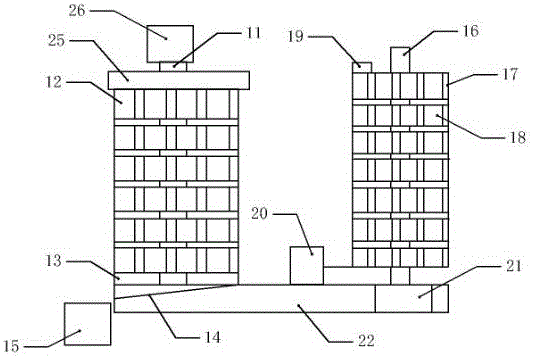
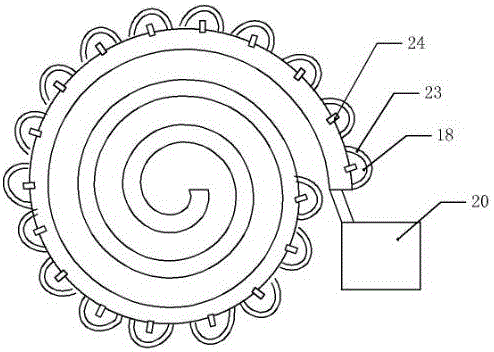
[0017] First shaft 11, gear 12, filter screen 13, partition 14, collection tank 15, second shaft 16, tape 17, air bag 18, buckle 19, blower 20, cylinder 21, base 22, fine sandpaper 23, single To air inlet 24, baffle plate 25, motor 26.

[0018] Such as figure 1 The shown gear deburring device includes a hollow base 22, a first rotating shaft 11 is installed on the left side of the base 22, a second rotating shaft 16 is installed on the right side of the base 22, five gears 12 to be processed are pierced on the first rotating shaft 11, The tooth slots of the gears 12 on the first rotating shaft 11 communicate vertically, the upper end of the first rotating shaft 11 is connected to the motor 26, the lower end of the first rotating shaft 11 is equipped with a filter screen 13 made of soft iron materia...


PUM

PropertyMeasurementUnit
Meshaaaaaaaaaa

Abstract

The invention relates to the technical field of gear machining, in particular to a gear deburring device. The gear deburring device comprises a hollow base. A first rotation shaft and a second rotation shaft are arranged on the two sides of the base correspondingly. A plurality of same to-be-machined gears penetrate the first rotation shaft. Tooth grooves of the gears on the first rotation shaft are opposite in the longitudinal direction. The first rotation shaft is provided with a motor. A winding belt is wound around the second rotation shaft, and longitudinal strip-shaped grooves and transverse strip-shaped grooves are evenly formed in the winding belt and divide the winding belt into the grid shape. Air bags are arranged in grids on the winding belt and externally provided with elastic fine abrasive paper. A hollow interlayer is arranged on the winding belt. One-way air inlet holes communicating with the hollow interlayer are formed in the connecting positions of the air bags and the winding belt. The hollow interlayer of the winding belt is connected with an air blower. The lower end of the second rotation shaft is connected with an air cylinder. The problems that the process of deburring between teeth of the gears is not uniform, consequently, dull polish patterns exist between the gears obtained after being deburred, and the tooth profile of the gears is damaged are solved.

Description

technical field [0001] The invention relates to the technical field of gear processing, in particular to a gear deburring device. Background technique [0002] Gear is a mechanical element with teeth on the wheel rim, which can continuously mesh and transmit motion and power. It appeared very early in the application of transmission. Because of the stability and continuity of transmission, it is widely used in various fields of machinery; It is one of the essential components in the gearbox. The quality of the gear determines the stability of the transmission, the accuracy of the reduction ratio, and the vibration and noise transmitted. In the cycloid reducer, the tooth profile accuracy of the gear The requirements for smoothness and smoothness are high. At the same time, due to the special shape of the gear, ordinary grinding equipment is likely to damage the tooth profile during the deburring process, making it difficult to mechanize the deburring work of the gear. [000...

Claims


Application Information

Patent Timeline
IPC IPC(8): B24B9/04B24B41/00B24B47/00B24B55/12
CPCB24B9/04B24B41/00B24B47/00B24B55/12
Inventor 曾义杰
Owner 重庆和烁精密锻造有限公司
Why Eureka
Try Eureka