
Grinding light machine semi -automatic feeding mechanism

A semi-automatic, loading and unloading technology, applied in the field of grinding and scanning machines, can solve the problems of weak glass suction, frying machine, low degree of automation, etc., and achieve the effect of avoiding vacuum leakage

Active Publication Date: 2022-08-09
SHENZHEN HANJIANG AUTOMATION SCI & TECH CO LTD
View PDF0 Cites 0 Cited by
  • Summary
  • Abstract
  • Description
  • Claims
  • Application Information

AI Technical Summary

Problems solved by technology

The existing grinding and sweeping machine has a low degree of automation, and it is necessary to manually place the glass piece by piece on the carrier plate of the grinding and sweeping machine, and then absorb the glass through the vacuum holes on the carrier plate to carry out the subsequent grinding and sweeping process. After finishing the grinding and sweeping of the glass, it is necessary to manually remove the glass from the carrier plate one by one
[0003] When glass is loaded, during the process of manually placing the glass, before the tray is completely filled with material, part of the vacuum holes on the tray are exposed and directly connected to the atmosphere, which makes the suction of the tray to the glass insufficient, which is likely to cause The glass on the other carrier discs being ground is separated and broken into the disc cover, and the phenomenon of frying occurs; the same is true when the material is unloaded. When the glass on the carrier disc is removed one by one, the glass that has been removed corresponds to The vacuum hole of the vacuum hole is restored to be directly connected to the atmosphere. When only the last few pieces of glass are left, because most of the vacuum holes are connected to the atmosphere, the suction force of the carrier plate on the glass becomes very weak, which will easily cause the glass to fall off and break.

Method used


Image

  • Grinding light machine semi -automatic feeding mechanism
  • Grinding light machine semi -automatic feeding mechanism
  • Grinding light machine semi -automatic feeding mechanism

Examples


Embodiment Construction

[0031] The present application will be further described in detail below with reference to the accompanying drawings and specific embodiments. It should be understood that the following exemplary embodiments and descriptions are only used to explain the present invention, but not to limit the present invention, and, in the case of no conflict, the embodiments in the present application and the features in the embodiments can be combined with each other .

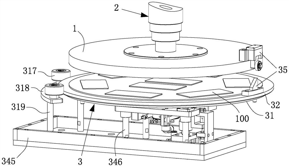
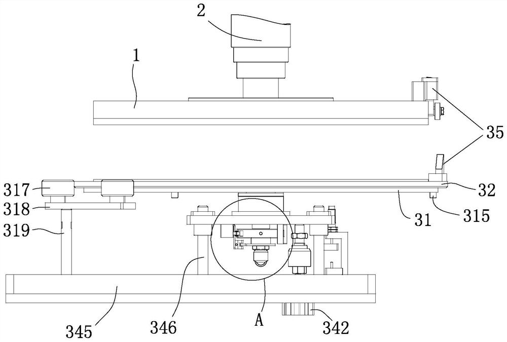
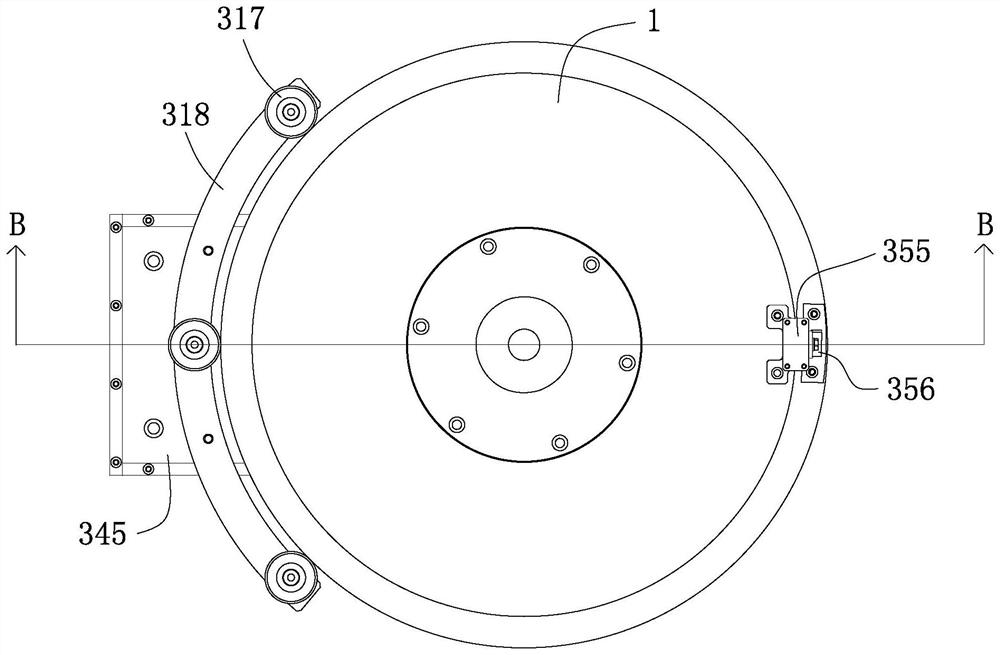
[0032] like Figure 1 to Figure 15 As shown, an embodiment of the present invention provides a semi-automatic loading and unloading mechanism for a grinding and sweeping machine, including a carrier plate 1 for vacuum adsorption of a sheet material 100 by an external vacuum system (not shown in the figure), a carrier plate 1 for driving the carrier plate 1 The carrier disk drive module 2 that rotates and lifts, a control module (not shown in the figure) for controlling the working state of the carrier disk drive module 2, a...


PUM


Abstract

The embodiment of the present invention discloses a semi-automatic loading and unloading mechanism of a grinding and sweeping machine, which includes a carrier plate externally connected to a vacuum system to perform vacuum adsorption on sheet materials, a carrier disk drive module for driving the rotation and lifting of the carrier disk, and a carrier disk drive module for controlling the carrier disk. The control module of the working state of the disk drive module and the transfer module arranged under the carrier disk for preloading the sheet material, the transfer module includes a carrier table, a transfer disk for carrying the sheet material, and a vacuum for generating a vacuum to The suction assembly for sucking the sheet material on the middle turntable from the bottom, and the lift drive assembly for driving the lifting and lowering of the loading table, the middle turntable is placed on the loading table and is positioned relative to the loading table in the circumferential direction, and the lifting drive assembly and suction The components are all electrically connected to the control module and cooperate with the carrier disk drive module under the control of the control module. In the embodiment of the present invention, the transfer module is used to realize that all the sheet materials are the same as above and the same as the bottom during the loading and unloading process, so as to avoid the vacuum leakage of the carrier tray from damaging the sheet materials, and improve the production efficiency.

Description

technical field [0001] The invention relates to the technical field of grinding and sweeping machines, in particular to a semi-automatic loading and unloading mechanism of the grinding and sweeping machine. Background technique [0002] In the glass production process, it is usually necessary to use a grinding and polishing machine to grind and scan the glass to meet the factory requirements. The existing grinding and scanning machine has a low degree of automation, and it is necessary to manually place the glass piece by piece on the carrier disc of the grinding and scanning machine, and then adsorb the glass through the vacuum holes on the carrier disc to carry out the subsequent grinding and scanning process. After the grinding and sweeping of the glass is completed, the glass needs to be manually removed from the carrier plate piece by piece. [0003] When the glass is loaded, in the process of manually placing the glass, before the carrier plate is not completely fille...

Claims


Application Information

Patent Timeline
Patent Type & Authority Patents(China)
IPC IPC(8): B65G49/06B24B41/00
CPCB65G49/061B24B41/005Y02P40/57
Inventor 杨智军易真江雷志奇
Owner SHENZHEN HANJIANG AUTOMATION SCI & TECH CO LTD
Learn More