Amorphous annealing furnace

An annealing furnace, amorphous technology, applied in the direction of furnace, furnace type, heat treatment furnace, etc., can solve the problems of affecting the working effect of the annealing furnace, waste of resources, low cooling rate, etc.

Inactive Publication Date: 2017-05-24
JIANGSU YANGDONG ELECTRIC
View PDF6 Cites 2 Cited by
  • Summary
  • Abstract
  • Description
  • Claims
  • Application Information

AI Technical Summary

Problems solved by technology

[0004] The currently used amorphous alloy annealing furnace has the defect of large temperature difference inside the annealing furnace, which causes

Method used


Image

  • Amorphous annealing furnace

Examples


Embodiment 1

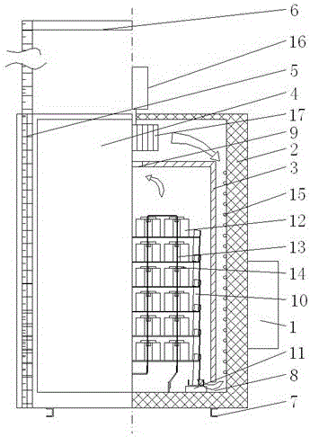
[0020] like figure 1 As shown, a kind of amorphous annealing furnace of the present invention comprises instrument box 1, furnace body and iron frame group, and furnace body comprises outer furnace wall 2, inner furnace wall 3 and door 4, and door 4 moves up and down through slide rail 5, The slide rail 5 is located on the outer furnace wall 2, and the top of the furnace body is provided with a door bracket 6, which replaces the opening of the double doors in the prior art, and the door is directly opened upward without occupying space. The bottom of the outer furnace wall 2 is provided with an external support 7, The inner furnace wall 3 is set inside the outer furnace wall 2, and a sealed chamber is formed between the outer furnace wall 2 and the door 4, and the chamber is sealed and filled with nitrogen gas. The addition of nitrogen gas can make the iron core bright, and the bottom of the inner furnace wall 3 has no bottom cover. A gap 8 is provided between the bottom of th...


PUM


Abstract

The invention relates to an amorphous annealing furnace which comprises an instrument box, a furnace body and an iron stand group, wherein the furnace body comprises an outer furnace wall, an inner furnace wall and a door; a sealed chamber is formed between the outer furnace wall and the door; no bottom cover is arranged at the bottom of the inner furnace wall; a gap is reserved between the bottom of the inner furnace wall and the bottom of the outer furnace wall; a gas circulation port is formed at the top center of the inner furnace wall; the iron stand group is arranged in the inner furnace wall; amorphous iron cores are placed on the iron stand group; a conductive copper bar is arranged between the amorphous iron cores; a heating pipe is arranged on the inner wall of the outer furnace wall; the instrument box is fixed on one side of the exterior of the outer furnace wall and controls the annealing furnace; a motor is arranged at the top of the outer furnace wall and drives a fan; and the fan is positioned at the center between the outer furnace wall and the inner furnace wall. Compared with the prior art, the amorphous annealing furnace provided by the invention has the following advantages: with the addition of nitrogen, the iron cores become bright; the door is directly opened upward without occupying space; since the size of the iron stand is adjustable, the annealing of multi-size iron cores is facilitated; and through full-automatic control, the overall annealing efficiency of the amorphous alloy iron cores is effectively improved.

Description

technical field [0001] The invention relates to an amorphous annealing furnace, belonging to the technical field of annealing furnaces. Background technique [0002] At present, the materials for making transformer iron core mainly include silicon steel strip and amorphous alloy. Compared with silicon steel strip, amorphous alloy is a more energy-saving material for manufacturing transformer iron core. Amorphous alloy is produced by rapid rapid cooling and solidification, and its physical state is that the metal atoms are arranged in a disordered amorphous manner, which is more conducive to magnetization and demagnetization. This material is used in the transformer core, and the transformer magnetization process is very easy, thereby greatly reducing the no-load loss of the transformer. From the point of view of the reduction of the no-load loss of the transformer, the amorphous alloy strip is incomparable to all the current silicon steel strips of various grades. [0003]...

Claims


Application Information

Patent Timeline
IPC IPC(8): C21D1/26C21D1/74C21D9/00
CPCC21D1/26C21D1/74C21D9/0068C21D2201/03
Inventor 李涛王扬王忠如邵振宏黄树旺
Owner JIANGSU YANGDONG ELECTRIC
Why Eureka
Try Eureka