Anti-seismic node of reinforced concrete column beam

A reinforced concrete, column-beam technology, applied in the direction of earthquake resistance, building types, buildings, etc., can solve the problems of overall structural failure, safety hazards, failure to achieve the design goals of strong columns and weak beams, etc., to protect the node structure and prevent structural failure Effect

Inactive Publication Date: 2017-05-24
QINGDAO TECHNOLOGICAL UNIVERSITY
View PDF0 Cites 4 Cited by
  • Summary
  • Abstract
  • Description
  • Claims
  • Application Information

AI Technical Summary

Problems solved by technology

However, under the actual earthquake, the column ends are very vulnerable to damage, and the design goal of "strong column and weak beam" cannot be achieved, resulting in failure of the overall structure and serious safety hazards

Method used


Image

  • Anti-seismic node of reinforced concrete column beam
  • Anti-seismic node of reinforced concrete column beam
  • Anti-seismic node of reinforced concrete column beam

Examples


Embodiment 1

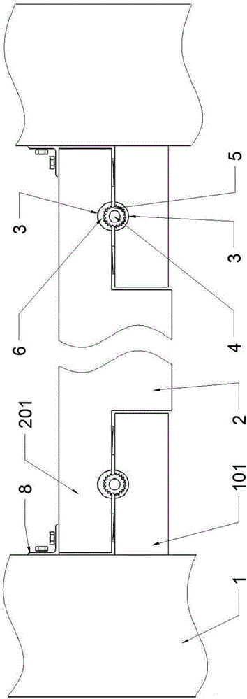
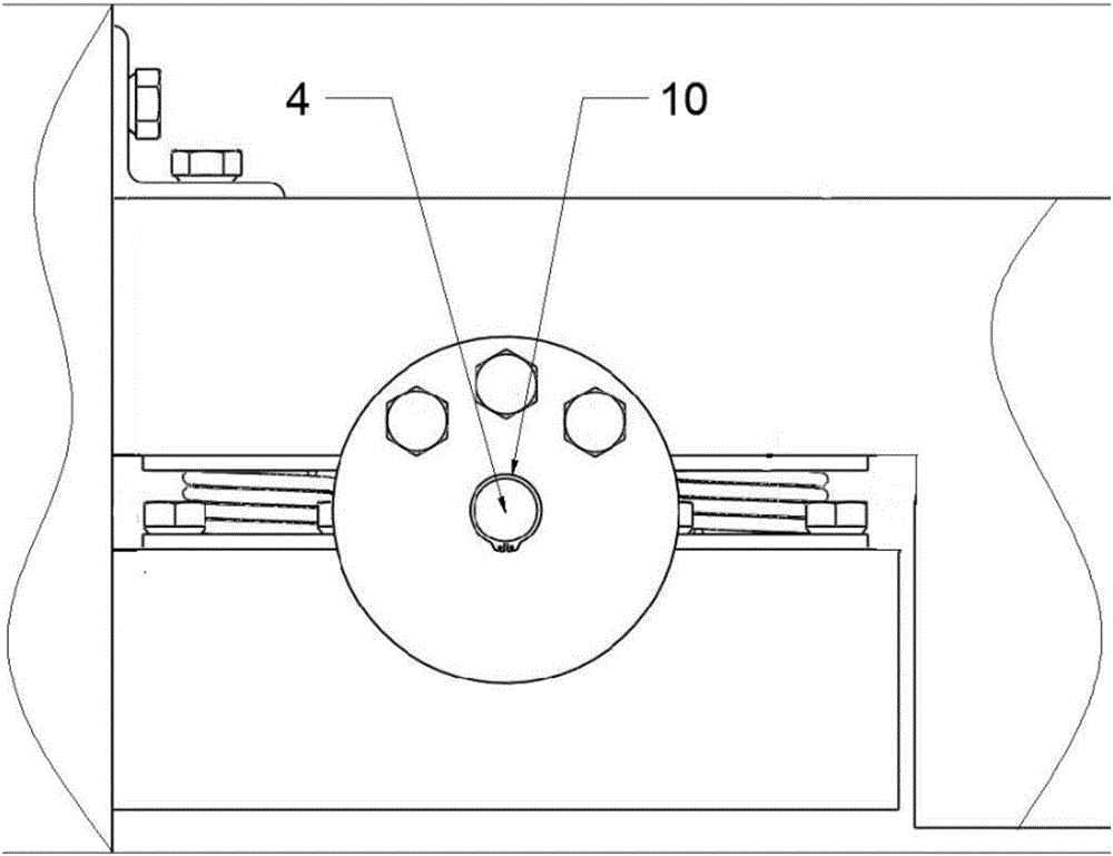
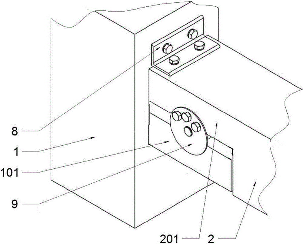
[0039] Such as Figure 1 to Figure 13 As shown, a reinforced concrete column-beam seismic joint according to the present invention includes a frame column 1, the frame column 1 extends outward to form a corbel 101, and the two ends of the frame beam 2 between the frame columns 1 extend outward A protruding part 201 matching with the corbel 101 is formed, the upper surface of the corbel 101 and the lower surface of the protruding part 201 are provided with mutually matching grooves 3, and the groove 3 is pre-embedded with a set The internal gear 5 fixed on the rotating shaft 4 matches the external gear 6 , and the rotating shaft 4 is fixed between the grooves 3 through the fixing ring 7 pre-embedded in the corbel 101 . During an earthquake, the friction loss between the internal gear 5 and the external gear 6 causes the frame beam 2 and the frame column 1 to rotate relative to the rotating shaft 4 to form a plastic hinge structure to protect the structure and prevent structural...

Embodiment 2

[0050] Such as Figure 14 to Figure 17 As shown, in this embodiment, preferably, the cross-sectional shape of the teeth of the internal gear 5 and the external gear 6 is triangular, so that a sufficiently large frictional resistance is generated between the internal gear 5 and the external gear 6 .

[0051]Preferably in this embodiment, a spring 11 is installed between the corbel 101 and the protrusion 201, the spring 11 is pre-embedded in the corbel 101, and the springs 11 located on both sides of the rotating shaft 4 can limit the rotation range of the frame beam 2, Avoid collision damage between the corbel 101 and the frame beam 2 caused by excessive rotation range or excessive rotation.

[0052] Preferably in this embodiment, flexible waterproof material 12 is filled between the corbel 101 and the frame beam 2, between the protruding part 201 and the frame column 1, and between the corbel 101 and the protruding part 201, so as to prevent the frame column 1 from There is n...


PUM


Abstract

The invention relates to an architectural structure node and in particular to an anti-seismic node of a reinforced concrete column beam. The anti-seismic node of the reinforced concrete column beam comprises a frame column. The frame column is outwards extended to form a bracket. Two ends of a frame beam between the frame columns are outwards extended to form a bulge part matched with the bracket. The upper surface of the bracket and the lower surface of the bulge part are provided with mutually matched grooves. Each groove is pre-embedded with an outer gear matched with an inner gear sheathed and fixed on a rotation shaft. The rotation shaft is fixed between the grooves through a fixing ring pre-embedded in the bracket. The split-type connection is formed between the frame column and the frame beam, so the beam end forms the plastic hinge structure in the earthquake, the node structure can be effectively protected, and the structure failure is prevented.

Description

technical field [0001] The invention relates to a building structure node, in particular to a reinforced concrete column-beam anti-seismic node. Background technique [0002] In civil engineering, a frame beam is a beam connected at both ends to frame columns. At present, there are mainly two types of reinforced concrete frame structures, one is the cast-in-place reinforced concrete frame structure, the frame beams and frame columns form a unified whole; the other is the assembled integral frame structure, the frame beams and frame columns are prefabricated parts , connected into a whole by means of welding or bolting. Under the action of vertical load, the frame beam bears the load and transmits it to the frame column, which is an important component of the structure; under the action of horizontal load, it is hoped that a plastic hinge will appear at the end of the beam in the design, and the seismic energy will be dissipated through the plastic hinge rotation. In order ...

Claims


Application Information

Patent Timeline
Patent Type & Authority Applications(China)
IPC IPC(8): E04B1/20E04B1/58E04B1/98E04H9/02
CPCE04B1/20E04B1/58E04H9/021
Inventor 宁宁张春巍于德湖许卫晓
Owner QINGDAO TECHNOLOGICAL UNIVERSITY
Why Eureka
Try Eureka