Visible artificial sand filling and oil flooding device with injection-production liquid level adjustment function, and application thereof

An artificial and oil displacement technology, applied in the field of reservoir physical simulation, can solve the problems of cumbersome operation process, inability to simulate, lack of effective means, etc., and achieve the effect of simple device structure, convenient manufacture, and optimized well pattern layout

Inactive Publication Date: 2017-05-24
TECHNICAL INST OF PHYSICS & CHEMISTRY - CHINESE ACAD OF SCI
View PDF13 Cites 6 Cited by
  • Summary
  • Abstract
  • Description
  • Claims
  • Application Information

AI Technical Summary

Problems solved by technology

The third model uses a three-dimensional simulation device to simulate various types of well patterns such as reverse five-point and reverse nine-point, but the device is complicated to manufacture and the operation process is cumbersome. More importantly, the model only considers the The layout does not involve the problem of liquid level difference at the injection and production ports
[0006] At present, the above-mentioned planar oil displacement model in the indoor stratigraphic simulation cannot simulate the influence of the liquid level difference at the injection and production ports on the recovery effect during the actual oil production process of the reservoir. On the other hand, the thickness of the model is relatively thin, and the sand filling volume is small , so there is a big limitation in the indoor simulation process
However, there is still a lack of effective means to study the influence of injection-production height difference on recovery, especially the development and improvement of related equipment has not been reported.

Method used


Image

  • Visible artificial sand filling and oil flooding device with injection-production liquid level adjustment function, and application thereof
  • Visible artificial sand filling and oil flooding device with injection-production liquid level adjustment function, and application thereof
  • Visible artificial sand filling and oil flooding device with injection-production liquid level adjustment function, and application thereof

Examples


Embodiment 1

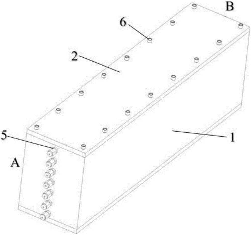
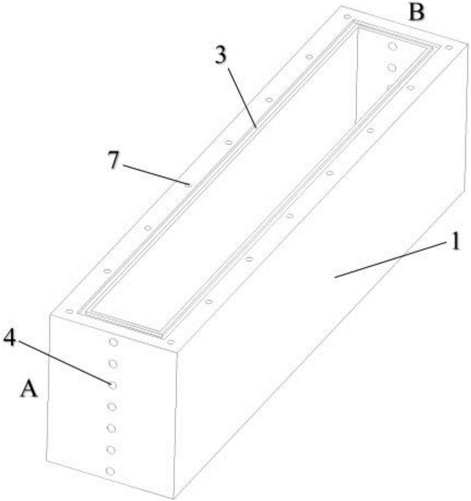
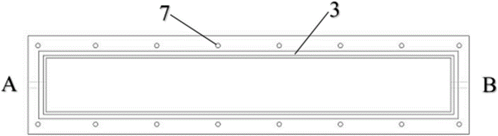
[0054] A visual artificial sand filling oil displacement device for adjusting the injection-production liquid level, such as Figure 1 to Figure 4 As shown, it includes an integrated frame 1 , a cover plate 2 , a groove 3 and a two-way joint element 5 . The cover plate 2 is composed of an upper cover and a lower cover; grooves 3 are provided on the inner wall edges of the upper and lower ends of the integrated frame 1; eight threaded holes A7 are arranged symmetrically and equidistantly on both sides of the upper and lower ends of the integrated frame 1; the cover plate 2 There is a threaded hole B 8 matching the threaded hole A7, and the cover plate 2 is fixedly connected to the integrated frame 1 through the screw 6 through the threaded hole A 7 and the threaded hole B 8; the A and B sides of the integrated frame 1 There are 7 threaded holes C4 equidistant and symmetrical respectively, and the two-way joint element 5 is fixedly connected through the threaded hole C4, wherein...

Embodiment 2

[0058] A visual artificial sand filling oil displacement device Ⅰ that can adjust the injection-production liquid level, such as Figure 5 As shown, its structure is the same as in Example 1, except that its external dimensions are 490mm long, 110mm wide, and 126mm high; four M8 threaded holes C are set on the side A of the integrated frame, which are 401 from bottom to top. ~404, four M8 threaded holes C symmetrical to side A are set on side B, 405~408 from top to bottom. Connector components.

[0059] The device is used for oil displacement operation. The specific indoor use process adopts the method described in Chinese patent CN103485769A, and the artificial sand filling oil displacement device of the present invention is used to replace the sand filling pipe assembly device in the patent. The steps of oil displacement operation are as follows:

[0060] 1) Before using the device, remove the upper cover.

[0061] 2) Prepare the sand. The sand is selected from the oil lay...

Embodiment 3

[0069] The device and operation steps that adopt are with embodiment 2, and difference is:

[0070] In step 6, the water injection rate is 0.5mL / min, and the device is subjected to water flooding operation to investigate the oil-water distribution ratio and study the law of water flooding remaining oil. This model adopts the injection-production method of low injection and high recovery, coupled with the high displacement speed, the remaining oil is less after water flooding; since this model is a sandstone hydrophilic model, the distribution of remaining oil is mainly distributed in the form of oil beads In the large pores, some remaining oil is distributed in the smaller pores.


PUM


Abstract

The invention discloses a visible artificial sand filling and oil flooding device with an injection-production liquid level adjustment function, and application thereof. The device comprises an integrated frame, a cover plate and two-way connector elements. The cover plate comprises an upper cover and a lower cover. A groove is formed in the edge of the inner wall of each of the upper end and the lower end of the integrated frame. A plurality of holes A are formed in two sides of each of the upper end face and the lower end face of the integrated frame symmetrically at equal intervals. The cover plate is provided with holes B matched with the holes A. Fixing elements penetrate the holes A and holes B to fixedly connect the cover plate with the integrated frame. At least one hole C is formed in each of the left side and the right side of the integrated frame. The integrated frame is connected with the two-way connector elements through the holes C. The two-way connector elements on one side are injection inlets, and the two-way connector elements on the other side are production outlets. The injection inlets and the production outlets have position differences. The visible artificial sand filling and oil flooding device has the advantages that injection-production wellhead liquid level differences in the actual oil production process of oil reservoirs are simulated through the height position differences between the injection inlets and the production outlets, and the visible artificial sand filling and oil flooding device has great significance in improving water-flooding development efficiency and the like.

Description

technical field [0001] The invention relates to the technical field of oil reservoir physical simulation. More specifically, it relates to a visual artificial sand filling oil flooding device for adjusting the injection-production liquid level and its application. Background technique [0002] In order to ensure the smooth development of field experiments in oilfields, before tertiary oil recovery technology is applied to mineral deposits, it is usually necessary to carry out indoor simulation experiments, and select the best implementation plan through the adjustment of various parameters, in order to better guide the actual application process in oilfields. [0003] At present, there are mainly three physical models for indoor evaluation by simulating the actual formation conditions and production process of reservoirs: (1) Physical models for simulating various heterogeneities such as low permeability, fractures, and fault blocks in reservoirs, such as China The Chinese ...

Claims


Application Information

Patent Timeline
Patent Type & Authority Applications(China)
IPC IPC(8): E21B43/16E21B43/22E21B43/20E21B49/00
CPCE21B43/16E21B43/20E21B49/00
Inventor 张妍妍施盟泉吴飞鹏张云龙张玉玺赵榆霞
Owner TECHNICAL INST OF PHYSICS & CHEMISTRY - CHINESE ACAD OF SCI
Why Eureka
Try Eureka